Membrane support material
a technology of supporting material and membrane, applied in the field of membrane supporting material, can solve the problems of reducing the robustness of bending and twisting, the inability to proceed through subsequent production line steps in an uninterrupted manner, and the reduction of lateral curvature, so as to reduce the weight per unit area, suppress the effect of lateral curvature and reduce the number of production line malfunctions
- Summary
- Abstract
- Description
- Claims
- Application Information
AI Technical Summary
Benefits of technology
Problems solved by technology
Method used
Image
Examples
first embodiment
[First Non-Woven Fiber Sheet Processing]
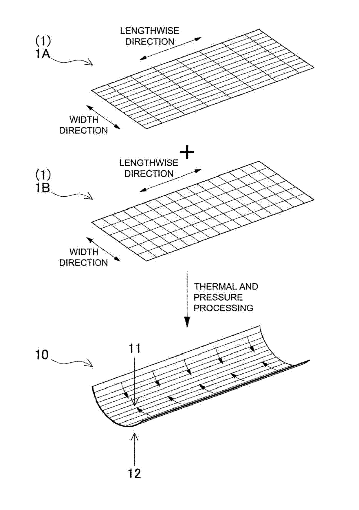
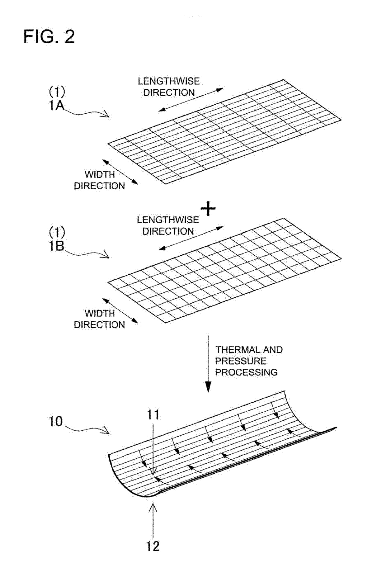
[0060]56% polyethylene-terephthalate (PET) drawn fibers with a 7 μm diameter and 5 mm length and 44% unstretched PET fibers with a 11 μm diameter and 5 mm length were suitably dispersed in water inside a tank (called a chest in paper manufacturing). The fiber concentration of the aqueous slurry was adjusted to 0.05%, the slurry was delivered onto an inclined-wire, the flow-rate of the slurry and speed of the inclined-wire were adjusted to regulate the longitudinal-to-lateral tensile strength ratio (k), and fibers were aggregated to form wet-processed non-woven fiber sheet A. The processed sheet A was cut to a 50 mm width and gripped at a 180 mm interval by the tensile strength measurement tool. Tensile strength in the lengthwise direction (f2) and tensile strength in the width direction (f1) were measured, and the ratio (f2 / f1) of longitudinal tensile strength (f2) to lateral tensile strength (f1), which is longitudinal-to-lateral tensile stre...
second embodiment
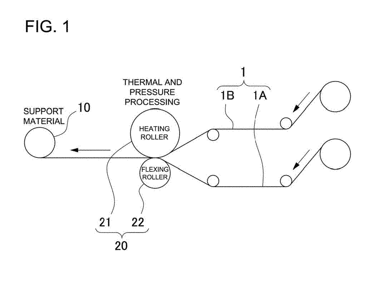
[0064]Except for second non-woven fiber sheet processing where wet-processed non-woven fiber sheet E with a weight per unit area of 38 g / m2 and longitudinal-to-lateral tensile strength ratio (k) of 3.6 was fabricated, this embodiment is the same as the first embodiment. First non-woven fiber sheet processing to produce sheet A with a weight per unit area of 38 g / m2 and longitudinal-to-lateral tensile strength ratio (k) of 6.7 was the same as in the first embodiment. The two processed non-woven fiber sheets (A and E) were laminated together with the heating roller 21 and flexing roller 22 of the thermal press equipment 20 to form a single sheet via thermal and pressure processing under the same conditions as in the first embodiment.
[0065]Support material for the second embodiment processed as described above had a weight per unit area of 78 g / m2, a thickness of 93 μm, and a porosity of 0.7 cc / cm2 / sec. Further, support material was cut to a 15 mm width and gripped at a 180 mm interval...
third embodiment
[0066]Except for first non-woven fiber sheet processing where wet-processed non-woven fiber sheet B with a weight per unit area of 38 g / m2 and longitudinal-to-lateral tensile strength ratio (k) of 3.6 was fabricated, this embodiment is the same as the first embodiment. Second non-woven fiber sheet processing to produce sheet F with a weight per unit area of 38 g / m2 and longitudinal-to-lateral tensile strength ratio (k) of 1.8 was the same as in the first embodiment. The two processed non-woven fiber sheets (B and F) were laminated together with the heating roller 21 and flexing roller 22 of the thermal press equipment 20 to form a single sheet via thermal and pressure processing under the same conditions as in the first embodiment.
[0067]Support material for the third embodiment processed as described above had a weight per unit area of 78 g / m2, a thickness of 93 μm, and a porosity of 0.9 cc / cm2 / sec. Further, support material was cut to a 15 mm width and gripped at a 180 mm interval ...
PUM
| Property | Measurement | Unit |
|---|---|---|
| thickness | aaaaa | aaaaa |
| melting point | aaaaa | aaaaa |
| length | aaaaa | aaaaa |
Abstract
Description
Claims
Application Information
 - R&D
- Intellectual Property
- Life Sciences
- Materials
- Tech Scout
- Unparalleled Data Quality
- Higher Quality Content
- 60% Fewer Hallucinations
Browse by: Latest US Patents, China's latest patents, Technical Efficacy Thesaurus, Application Domain, Technology Topic, Popular Technical Reports.
© 2025 PatSnap. All rights reserved.Legal|Privacy policy|Modern Slavery Act Transparency Statement|Sitemap|About US| Contact US: help@patsnap.com


