Sensor control circuit and electronic apparatus

a technology of electronic equipment and control circuit, applied in the direction of electric programme control, acceleration measurement using interia force, instruments, etc., can solve the problems of large circuit area, inability to recover, and easy submerged noise of the sensor, etc., to achieve enhanced driving capability

Active Publication Date: 2018-08-21
CSMC TECH FAB2 CO LTD
View PDF21 Cites 0 Cited by
  • Summary
  • Abstract
  • Description
  • Claims
  • Application Information

AI Technical Summary

Benefits of technology

[0015]Optionally, the switched capacitor integrator circuit includes a main amplifier, a chopper circuit connected between an input end of the switched capacitor integrator circuit and an input end of the main amplifier, and / or a sampling capacitance connected between an input end of the main amplifier and an output end of the main amplifier, wherein the chopper circuit is configured to reduce a low frequency noise and an input offset voltage of the input end of the main amplifier; and the sampling capacitance forms an auto-zero structure to reduce the input offset voltage of the input end of the main amplifier.
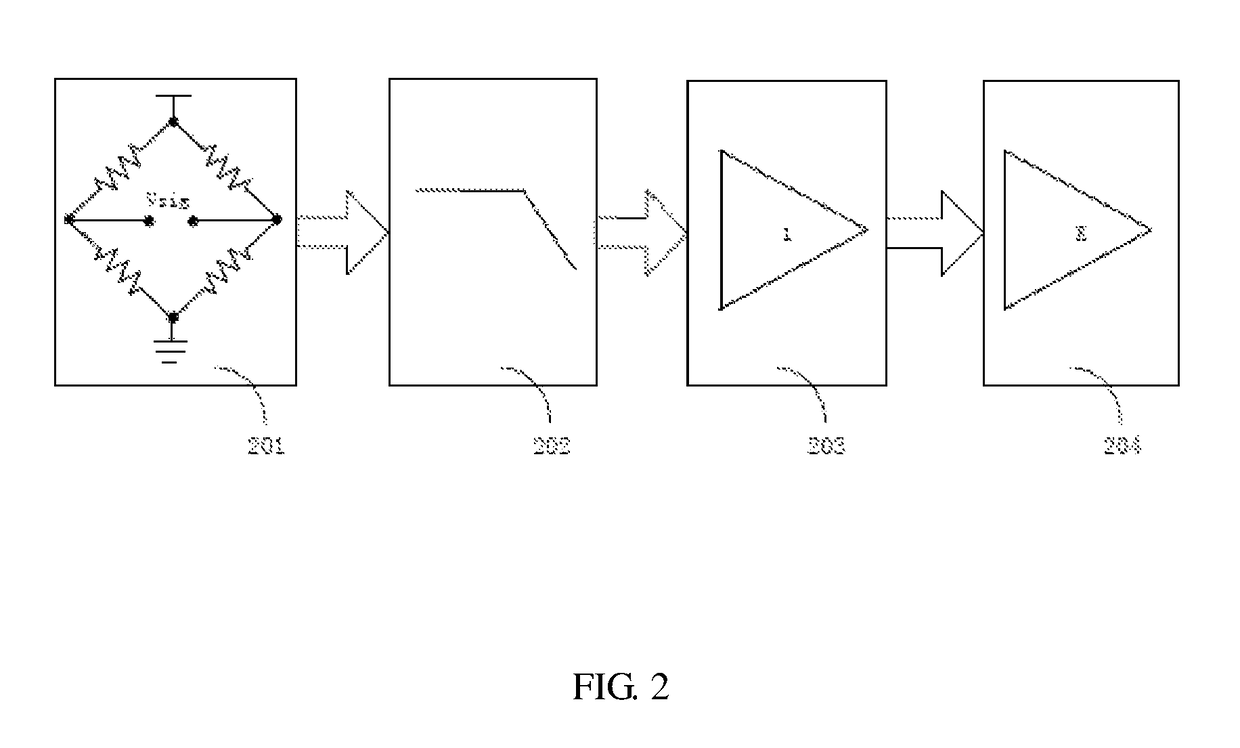
[0018]By virtue of providing the buffer circuit between the filter circuit and the amplifier circuit, the driving capability can be enhanced at some extent, thus ensuring a full sampling of the signal which is outputted by the filter circuit by the post-stage amplifier circuit.

Problems solved by technology

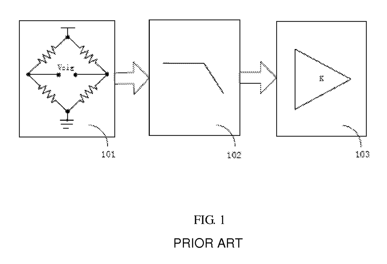
In general, an output of the sensor is a relative low voltage signal, because the signal is low, the signal of the sensor is easily submerged by noise and cannot be recovered.
Even the signal is amplified first, but the amplifier generates noise itself and such noise is amplified, such that the SNR (signal to noise ratio) of the amplified signal is also not improved.
For a continuous passive RC filter circuit, in order to realize a relative low bandwidth, it requires a relative large resistance and capacitance, thus usually leading to a large area of the circuit (chip).
At the same time, the sensor is in a working state all the time which causes great power consumption.
Because the signal amplitude is relative low, it demands a high requirement for the noise and linearity of the drive circuit, it is difficult to design.
The continuous active filter circuit requires using an amplifier, it consumes a large amount of current, and because the non-linearity of the amplifier itself, it causes a signal distortion, therefore, it demands a high requirement for designing the amplifier, increasing a designing difficulty.
When the signal through the filter circuit pass through the amplifier circuit, both the traditional resistance proportional amplifier circuit and the switched capacitance proportional amplifier circuit will amplify the noise signal at the time of amplifying the signal, especially for the low frequency noise (1 / f noise) of the amplifier itself, therefore, the SNR of the amplified signal decreases, causing the subsequent signal recovering to be more difficult.
Further, the passive RC filter circuit does not have a driving capability itself, thus further causing a non-sufficient sampling of the post-stage amplifier circuit.
Therefore, the common used sensor control circuit has problems such as non-sufficient sampling, circuit having a large area, great power consumption and weak noise suppression capability.

Method used


Image

  • Sensor control circuit and electronic apparatus
  • Sensor control circuit and electronic apparatus
  • Sensor control circuit and electronic apparatus

Examples


Embodiment Construction

[0026]In the following description, numerous specific details are set forth in order to provide a more thorough understanding of the present invention. However, it will be apparent to one skilled in the art that the present invention may be practiced without necessarily being limited to one or more of these specific details. In other instances, well-known technical features are not specific described, rather than in detail, in order to avoid obscuring the present invention.

[0027]This invention may, however, be embodied in many different forms and should not be constructed as limited to the embodiments set forth herein; rather, these embodiments are provided so that this disclosure will be thorough and complete, and will fully convey the scope of the invention to those skilled in the art. Like numbers refers to like elements throughout the accompanying drawings.

[0028]Terminology used herein merely describes the specific embodiments, and is not intended to limit the invention. When us...


PUM


Abstract

A sensor control circuit comprises a sensor (201), a filtering circuit (202), a buffering circuit (203), and an amplifying circuit (204). An output end of the sensor (201) is connected to an input end of the filtering circuit (202), an output end of the filtering circuit (202) is connected to an input end of the buffering circuit (203), and an output end of the buffering circuit (203) is connected to an input end of the amplifying circuit (204). Because the buffering circuit (203) is disposed between the filtering circuit (202) and the amplifying circuit (204), the sensor circuit has an advantage of full sampling. Further provided is an electronic apparatus using the sensor control circuit.

Description

CROSS REFERENCE TO RELATED APPLICATIONS[0001]This application is a national stage application (under 35 U.S.C. § 371) of PCT / CN2014 / 092723, filed Dec. 1, 2014, which claims benefit of Chinese Application No. CN 201310647877.5, filed Dec. 4, 2013; the contents of which are incorporated herein by reference in their entireties.FIELD OF THE INVENTION[0002]The invention relates to sensor technologies, and more particularly, relates to a sensor control circuit and an electronic device.BACKGROUND OF THE INVENTION[0003]As the development of the MEMS (Micro-electromechanical system) technology, the piezo-resistive acceleration sensor is extensively applied to many fields, due to a high sensitivity, a fast response, and a low electromagnetic interference. In general, an output of the sensor is a relative low voltage signal, because the signal is low, the signal of the sensor is easily submerged by noise and cannot be recovered. Even the signal is amplified first, but the amplifier generates n...

Claims


Application Information

Patent Timeline
Patent Type & Authority Patents(United States)
IPC IPC(8): H03F3/00H03G1/00G01P15/12G01P15/08H03H7/075H03F3/387H03F3/45
CPCH03F3/005G01P15/0802G01P15/123H03F3/387H03F3/45475H03H7/075H03G1/0094H03F2203/45514H03F2200/165H03F2200/261H03F2200/264H03F2203/45138G05B19/04
Inventor WANG, XUEYANZHANG, WEIYAN
Owner CSMC TECH FAB2 CO LTD
Why Eureka
Try Eureka