
High performance electric grill, method, and heat radiating module

a high-performance, electric grill technology, applied in the direction of electrical heating fuel, domestic stoves or ranges, lighting and heating equipment, etc., can solve the problems of only achieving good cooking performance, unable to achieve high-temperature vaporization of grease, and most of the radiant energy generated by heating elements is lost to the atmosphere, so as to achieve greater high-temperature cooking temperature, increase the effect of cooking heat flux and high efficiency

Active Publication Date: 2018-07-31
W C BRADLEY CO
View PDF47 Cites 66 Cited by
  • Summary
  • Abstract
  • Description
  • Claims
  • Application Information

AI Technical Summary

Benefits of technology

The solution achieves higher cooking temperatures, increased power density, reduced warm-up times, and improved smoke production for flavoring, while maintaining high efficiency and flare-up resistance, even with the lid open.

Problems solved by technology

However, this first type of electric grill suffers from the problem that the temperature of the heated cooking surface must be held below the ignition point of the grease so that fire will not occur at the point of cooking.
However, the required low temperature will not sufficiently vaporize the grease to produce the smoke necessary for flavoring the meat when grilling.
Unfortunately, in this second type of electric grill, good cooking performance can only be achieved by cooking with the lid closed as much as possible.
If the lid is open, the cavity is not only split into two open halves, but most of the radiant energy generated by the heating element is lost to the atmosphere with little effective retention by the food or by the open wire cooking grate.
However, this third type of grill, though presenting better performance, takes a long time to warm up to a sufficient operating temperature for prompt searing.
In addition, each of the prior art electric grills described above also suffers from a lack of power density.
This condition is driven by the wattage limitations of standard US residential electrical systems.
As a result, in less than ideal conditions, such as a cold windy day, the electrical cooking appliance may not produce adequate cooking results.

Method used


Image

  • High performance electric grill, method, and heat radiating module
  • High performance electric grill, method, and heat radiating module
  • High performance electric grill, method, and heat radiating module

Examples


Embodiment Construction

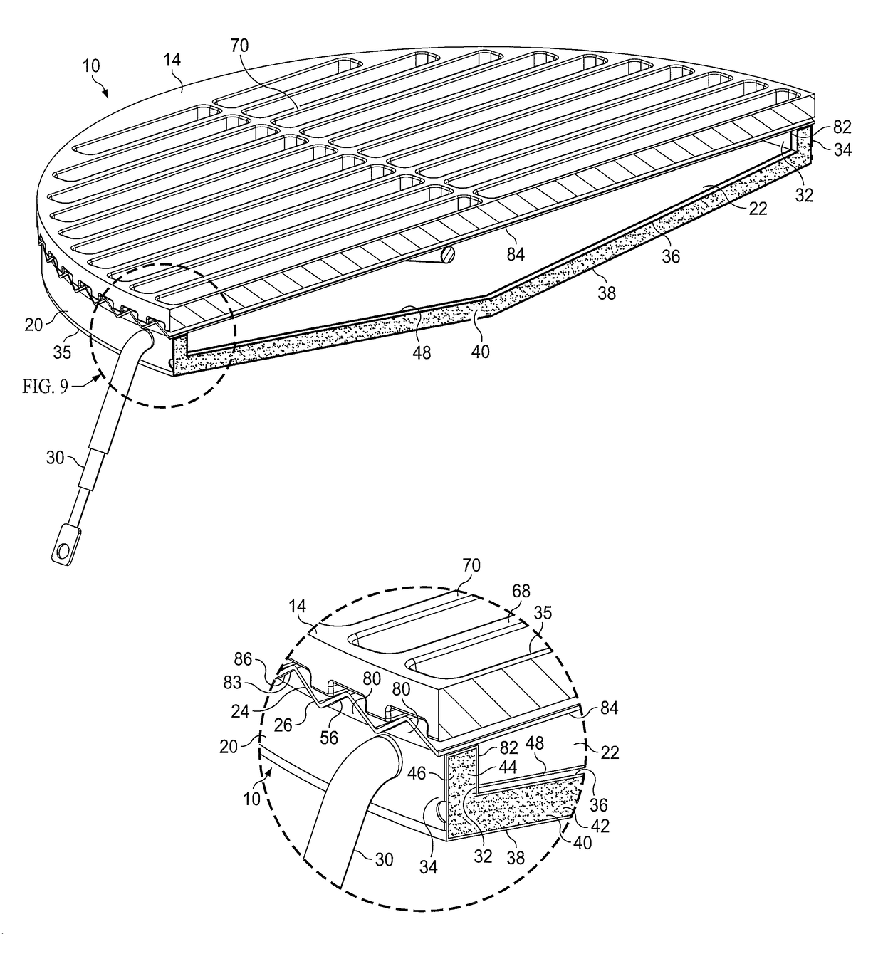
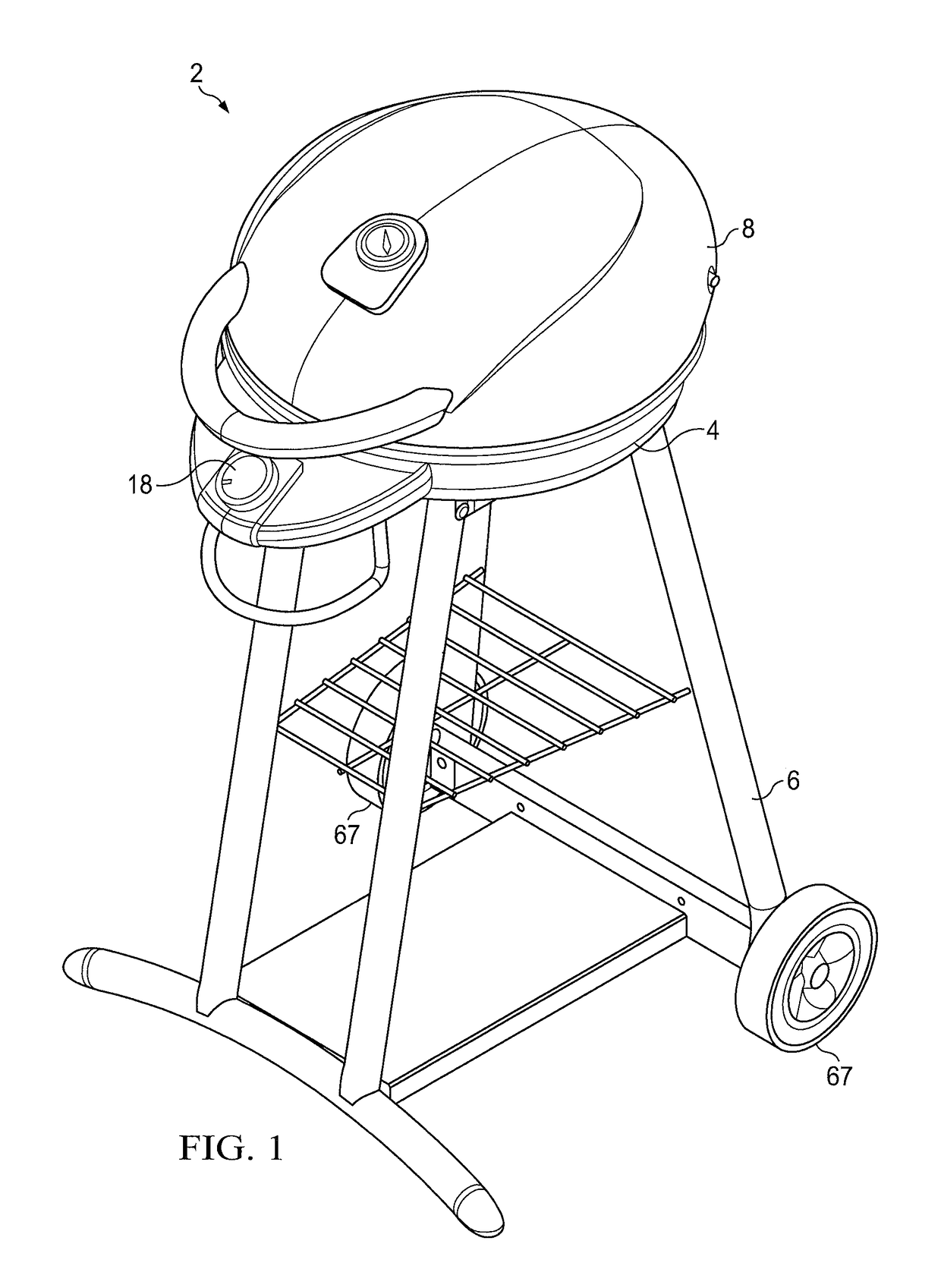
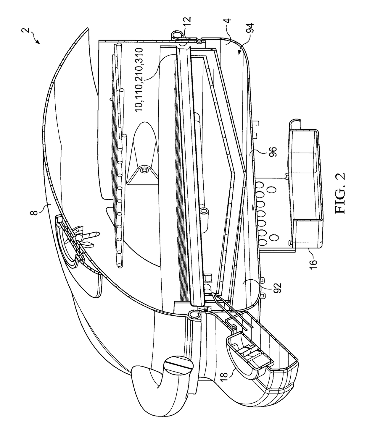
[0039]An embodiment 2 of an outdoor electric grill provided by the present invention is shown in FIGS. 1-3. The inventive electric grill 2 preferably comprises: a base housing 4; a support frame, housing, or other support structure 6 upon which the base housing 4 is mounted; a lid 8 which is pivotably attached to the base housing 4 or is otherwise provided for opening and closing the top of the base housing 4; an inventive electrically-powered heat radiating module 10 which is positioned within or at least partially within the upper portion 12 of the base housing 4; a food support grate 14 which is positioned on the heat radiating module 10; a drip pan or cup 16 in or beneath the base housing 4; and an exterior control panel 18 extending from the base housing 4.

[0040]An embodiment of the inventive electrically-powered heat radiating module 10 is further illustrated in FIGS. 3-9. The inventive module 10 preferably comprises: a module housing 20 having a heating cavity 22 therein; an ...


PUM


Abstract

An electric grill and method, and an electrically-powered heat radiating module which is removably or permanently positioned in the grill housing. The heat radiating module includes one or more electric heating elements which are preferably contained within a shallow heating cavity which is at least 95% closed to air flow into or out of the heating cavity and is also preferably insulated. Fat and water drippings from the food product flow around the heat radiating module rather than into the heating cavity. An infrared cooking grate assembly with a food support grate positionable on an emitter plate is also provided.

Description

RELATED CASE[0001]This application claims the benefit of U.S. Provisional Patent Application Ser. No. 62 / 040,016 filed on Aug. 21, 2014 and incorporates the provisional application by reference into this document as if fully set out at this point.FIELD OF THE INVENTION[0002]The present invention relates to electric grilling apparatuses and methods, and to an electric module for radiating heat energy for cooking food in an outdoor grill. The present invention also relates to infrared cooking grate assemblies.BACKGROUND OF THE INVENTION[0003]For many years, since the development of outdoor grilling appliances in the nineteen forties and fifties, there has been a desire for an effective electrically powered outdoor cooking appliance. It has long been believed that such a device might be made more convenient and easier to use, e.g., without requiring a special fuel like charcoal or propane. In recent years, the growing availability of electrical energy from renewable or otherwise enviro...

Claims


Application Information

Patent Timeline
Patent Type & Authority Patents(United States)
IPC IPC(8): A47J37/07F24C7/10F24C7/08A47J37/06H05B3/26
CPCA47J37/0709A47J37/0629F24C7/087H05B3/262F24C7/10H05B2203/032H05B2203/014F24C7/046
Inventor AHMED, MALLIK
Owner W C BRADLEY CO
Learn More