Yoke of rotary electric machine and manufacturing method thereof

A technology for rotating motors and manufacturing methods, applied in the field of yokes of magnetic circuits, can solve problems such as reducing heat capacity, reducing motor size or volume, and achieving the effect of reducing the overall quantity

Inactive Publication Date: 2007-06-27
DENSO CORP
View PDF1 Cites 2 Cited by
  • Summary
  • Abstract
  • Description
  • Claims
  • Application Information

AI Technical Summary

Problems solved by technology

However, although this technique reduces the heat capacity of the motor in addition to reducing its size or volume, there is a limit to the magnitude of the reduction
Therefore, there is also the technical question of how to increase the radiation capabilities of the motor

Method used


Image

  • Yoke of rotary electric machine and manufacturing method thereof
  • Yoke of rotary electric machine and manufacturing method thereof
  • Yoke of rotary electric machine and manufacturing method thereof

Examples


Embodiment

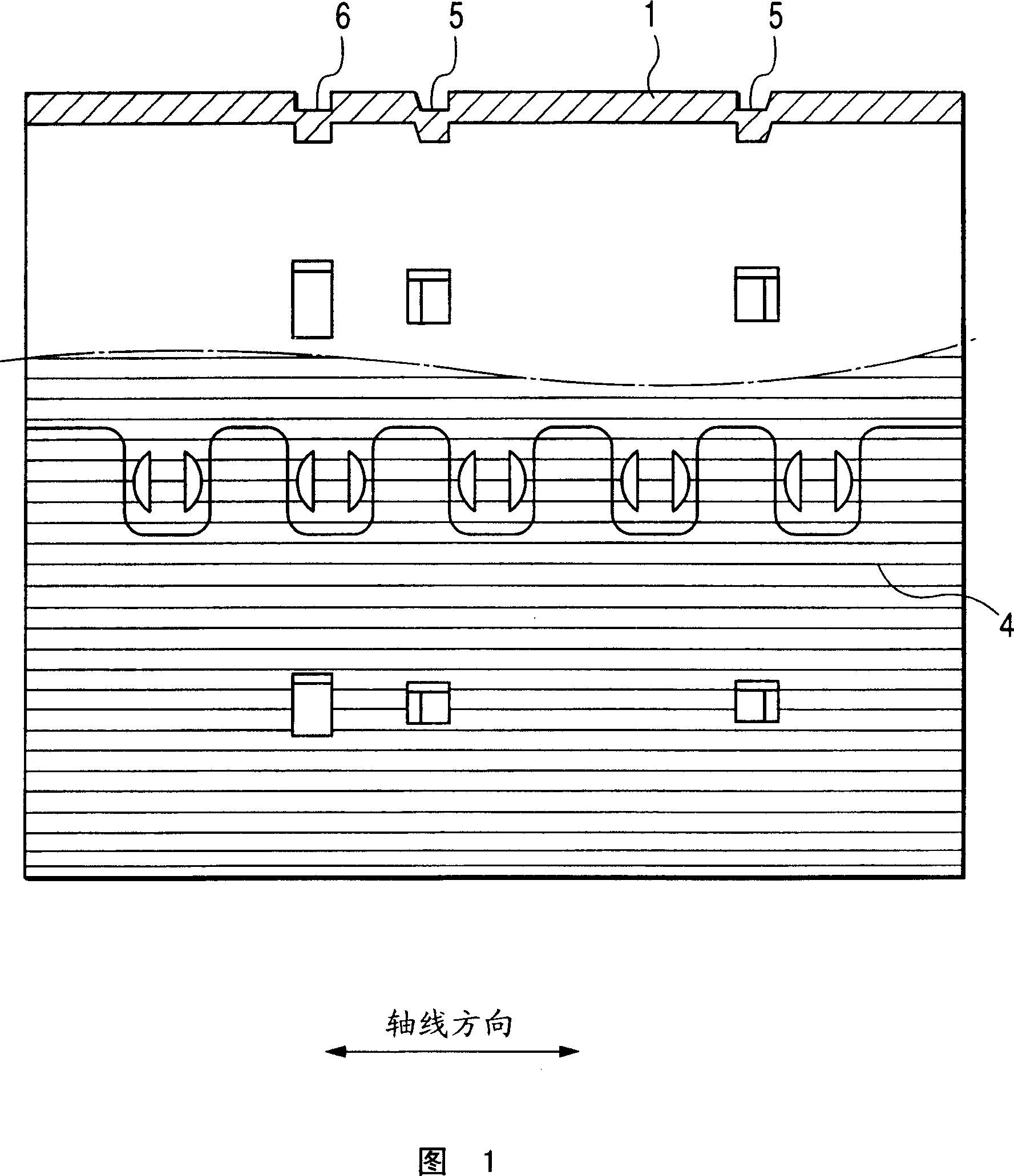
[0022] A yoke 1 for a rotary electric machine and a manufacturing method thereof according to an embodiment of the present invention will be described with reference to FIGS. 1-5.

[0023] FIG. 1 is a side view of a yoke according to an embodiment of the present invention, and FIG. 1 also shows a partial sectional view of the yoke.

[0024] The yoke 1 of this embodiment forms, for example, a starter motor (as a rotary electric machine) that starts an internal combustion engine mounted on a vehicle.

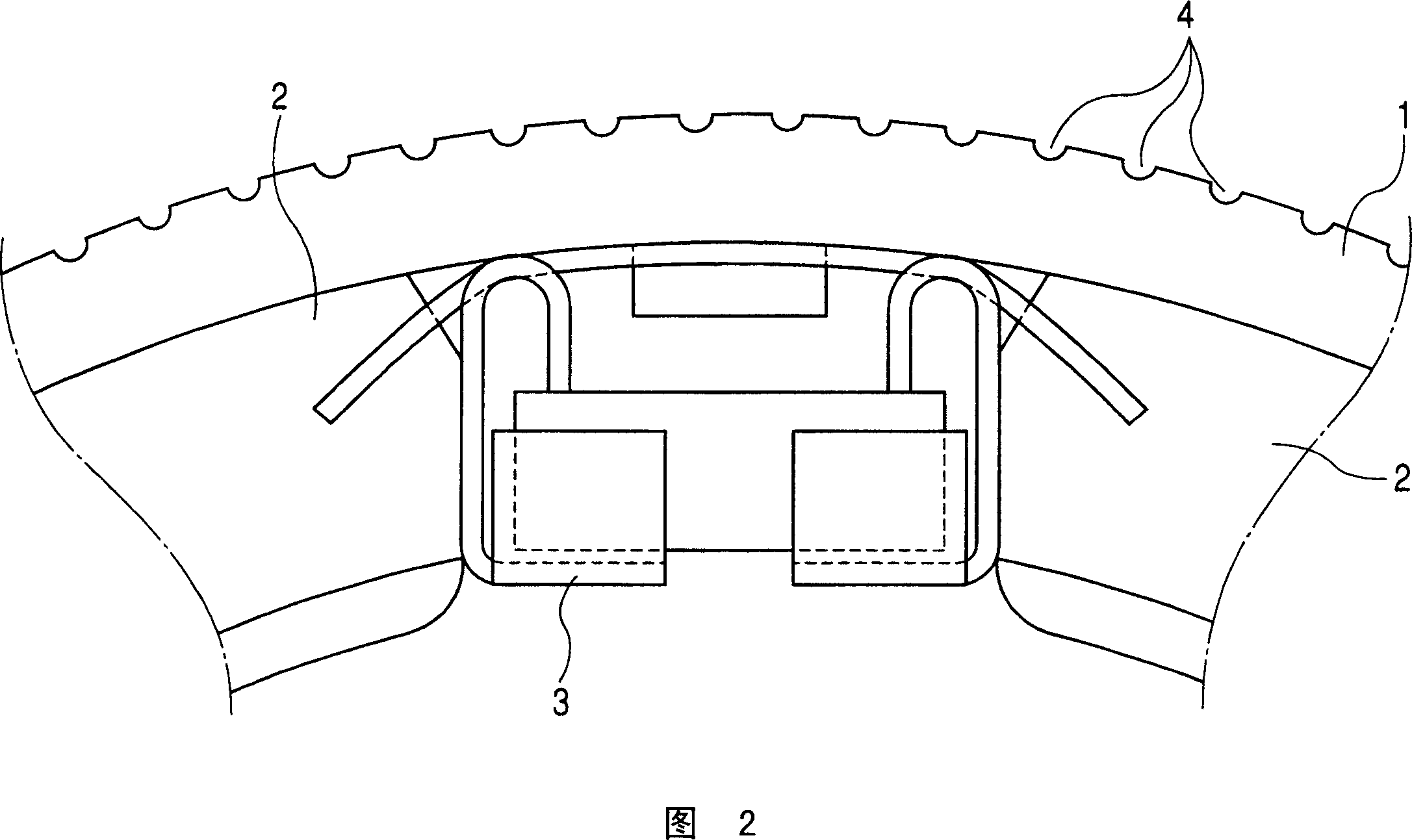
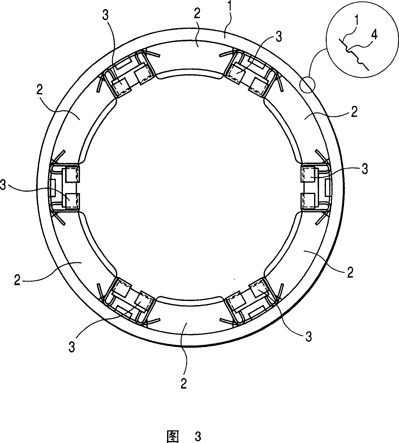
[0025] Fig. 3 is a plan view of the yoke assembled in the axial direction. As shown in FIG. 3 , a plurality of permanent magnets 2 are arranged and fixed on the inner periphery of the yoke 1 through magnet supporting members 3 . In particular, Figure 3 shows six permanent magnets 2 forming a yoke assembly as field magnets. As shown in FIG. 1 , a plurality of linear grooves 4 are formed on the outer peripheral surface of the yoke 1 at regular intervals along the entire periphery ...


PUM


Abstract

A yoke is produced by rolling up Zn-Al-Mg platinized steel plate of corrosion-resistance treatment where both ends thereof are tightly mated. On the outer peripheral surface of the yoke, plural linear grooves extending in the axis direction of the yoke are formed at a constant interval in the rolling step. Because the steel plate of corrosion-resistance treatment is prepared before initiating the rolling step, it is not necessary to perform coating and electroplating after making a cylindrical shaped yoke, namely, not necessary to perform any coating and electroplating after making the yoke, and the grooves are not filled with reaction products. This increases the radiation capability of the yoke because of increase of the entire surface area of the yoke. The Zn-Al-Mg platinized steel has a silver color and hardly absorbs radiant heat from an engine of a vehicle, and suppresses the increasing of the yoke temperature.

Description

technical field [0001] The present invention relates to a yoke forming a magnetic circuit of a rotating electric machine such as a starter mounted on a vehicle. Background technique [0002] For example, there are various techniques for manufacturing a yoke that is part of a rotating electric machine (or motor), such as a starter, mounted on a vehicle. Japanese Patent Publication No. JP S64-60247 has disclosed such techniques, drawing and punching and stuffing. The preceding techniques perform stretching operations to form cylindrical bodies from steel plates. The latter technique performs a blanking operation to form a cylindrical body, followed by a caulking operation to seal both ends of the cylindrical body. [0003] However, two conventional techniques require coating to cover the surface of the cylindrical body with a corrosion-resistant film, or electroplating and then cutting the corrosion-resistant film on both end surfaces of the cylindrical body to obtain a cond...

Claims


Application Information

Patent Timeline
Patent Type & Authority Applications(China)
IPC IPC(8): H02K1/06H02K15/02
CPCY10T29/53143H02K15/03Y10T29/49009H02K15/12Y10T29/49986H02K5/04H02K1/17H02K1/20H02K5/18
Inventor 村田光广
Owner DENSO CORP
Why Eureka
Try Eureka