
Injection member of molding machine and molding method

A molding machine and component technology, which is applied to the injection parts of the molding machine and the molding field, can solve the problems of longer cooling time, shorter molding cycle, and foreign matter mixed in molded products, so as to shorten the molding cycle and prevent the temperature from becoming excessively high. , the effect of shortening the cooling time

Active Publication Date: 2007-06-06
SUMITOMO HEAVY IND LTD
View PDF1 Cites 2 Cited by
  • Summary
  • Abstract
  • Description
  • Claims
  • Application Information

AI Technical Summary

Problems solved by technology

[0006] However, in the above-mentioned conventional injection device, if the molding cycle is shortened, the rotation speed of the measuring motor is increased, and the screw is rotated at a high speed, the pressure in the heating cylinder of the above-mentioned compression part will increase, and the resin will be burnt due to shear heat. excessively high temperature
As a result, the time for cooling the resin filled in the cavity space, that is, the cooling time becomes longer, and as a result, the molding cycle cannot be shortened.
[0007] In addition, as the temperature of the resin becomes excessively high, burns may occur in the resin, and foreign matter may be mixed in the molded product.
In addition, since the burnt resin adheres to the screw, it takes longer to maintain and manage the screw, that is, maintenance time
[0008] In addition, as the pressure in the heating cylinder increases, the force that pushes the screw against the inner peripheral surface of the heating cylinder increases, causing jamming between the heating cylinder and the screw.

Method used


Image

  • Injection member of molding machine and molding method
  • Injection member of molding machine and molding method
  • Injection member of molding machine and molding method

Examples


Embodiment Construction

[0039] Hereinafter, embodiments of the present invention will be described in detail with reference to the drawings. In addition, in this case, a molding machine, such as an injection molding machine, will be described.

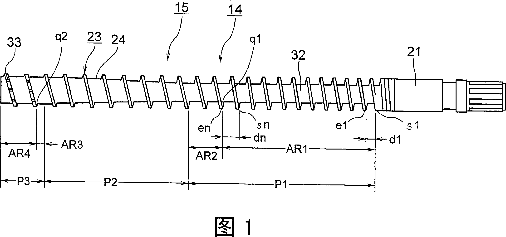
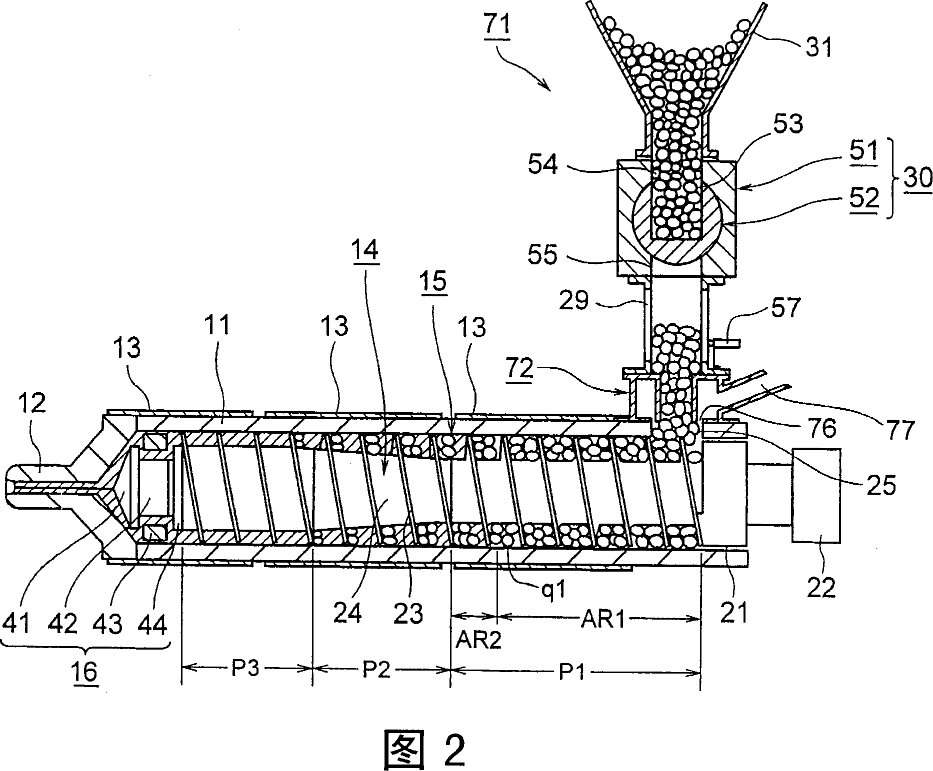
[0040] FIG. 1 is a schematic view of a main body portion of a screw according to a first embodiment of the present invention. Fig. 2 is a conceptual diagram of the injection device according to the first embodiment of the present invention.

[0041] In the figure, 11 is a heating cylinder as a cylinder member, an injection nozzle 12 is installed on the front end (left end in the figure) of the heating cylinder 11, and a plurality of heating cylinders are arranged on the outer periphery of the heating cylinder 11. Ring heater 13. In addition, in the heating cylinder 11, a screw 14 as an injection member is disposed rotatably and freely advancing and retreating (moving in the horizontal direction in the figure). And this screw 14 is comprised by the main-bod...


PUM


Abstract

An injection member of a molding machine capable of reducing a molding cycle and a maintenance time and preventing galling from occurring between a cylinder member and the injection member and a molding method. The injection member of the molding machine comprises a supply part (P1) to which a molding material is supplied through the molding material supply port of the cylinder member, a compression part (P2) melting and compressing the molding material supplied from the supply part (P1) thereto, and a weighing part (P3) weighing the molding material supplied from the compression part (P2) thereto. The supply part (P1) comprises a pressure regulating and switching point (q1) at a position apart a specified distance from the front end rearward and is divided into two parts through the pressure regulating and switching point (q1). The pressure of the molding material is gradually reduced in a pressure gradually reducing area (AR1) starting at the rear end of the supply part (P1) to the pressure regulating and switching point (q1). The pressure of the molding material is regulated in a pressure regulating area (AR2) starting at the pressure regulating and switching point (q1) to the front end of the supply part (P1).

Description

technical field [0001] The present invention relates to an injection part of a molding machine and a molding method. Background technique [0002] Conventionally, in a molding machine, such as an injection molding machine, resin, which is a molding material that is heated and melted in a heating cylinder as a cylinder member, is injected at high pressure and filled into the cavity space of a metal mold device. Cool and solidify in the cavity space to obtain a molded product. [0003] For this purpose, the above-mentioned injection molding machine has a mold clamping device and an injection device. The above-mentioned mold clamping device has a fixed platen and a movable platen, and the metal mold is closed and closed by moving the movable platen forward and backward by a mold clamping cylinder. Mold and mold opening. [0004] On the other hand, the injection device includes a heating cylinder for heating and melting resin supplied from a stocker, and an injection nozzle fo...

Claims


Application Information

Patent Timeline
Patent Type & Authority Applications(China)
IPC IPC(8): B29C45/50
CPCB29C45/50B29C45/60
Inventor 杉山智数面博义
Owner SUMITOMO HEAVY IND LTD
Learn More