
Integrated wind power generator

A wind power generator, integrated technology, applied in the direction of wind power generator components, wind power engine, wind power motor combination, etc.

Inactive Publication Date: 2007-05-16
IND METALURGICAS PESCARMONA I C & F IMPSA
View PDF0 Cites 6 Cited by
  • Summary
  • Abstract
  • Description
  • Claims
  • Application Information

AI Technical Summary

Problems solved by technology

These machines do not require a speed increaser, but are larger and heavier than machines belonging to another group

Method used


Image

  • Integrated wind power generator
  • Integrated wind power generator
  • Integrated wind power generator

Examples


Embodiment Construction

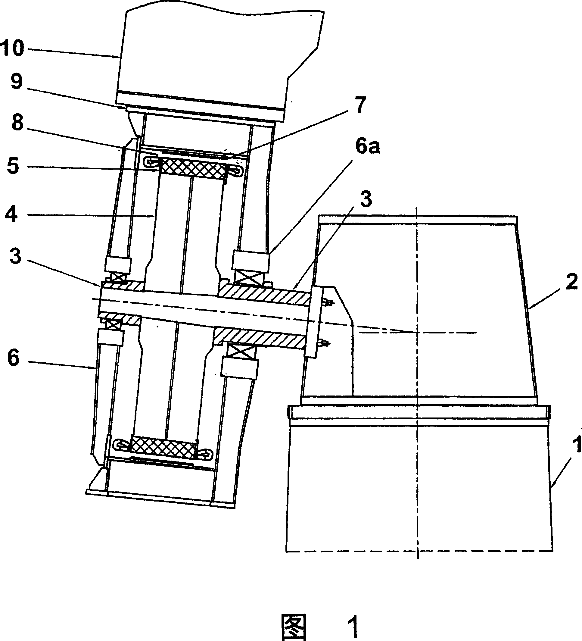
[0033] In general, the present invention consists of an integral wind generator that integrates the functions of a wind turbine and a generator in one device, which is functionally inseparable.

[0034] The device consists of two main elements:

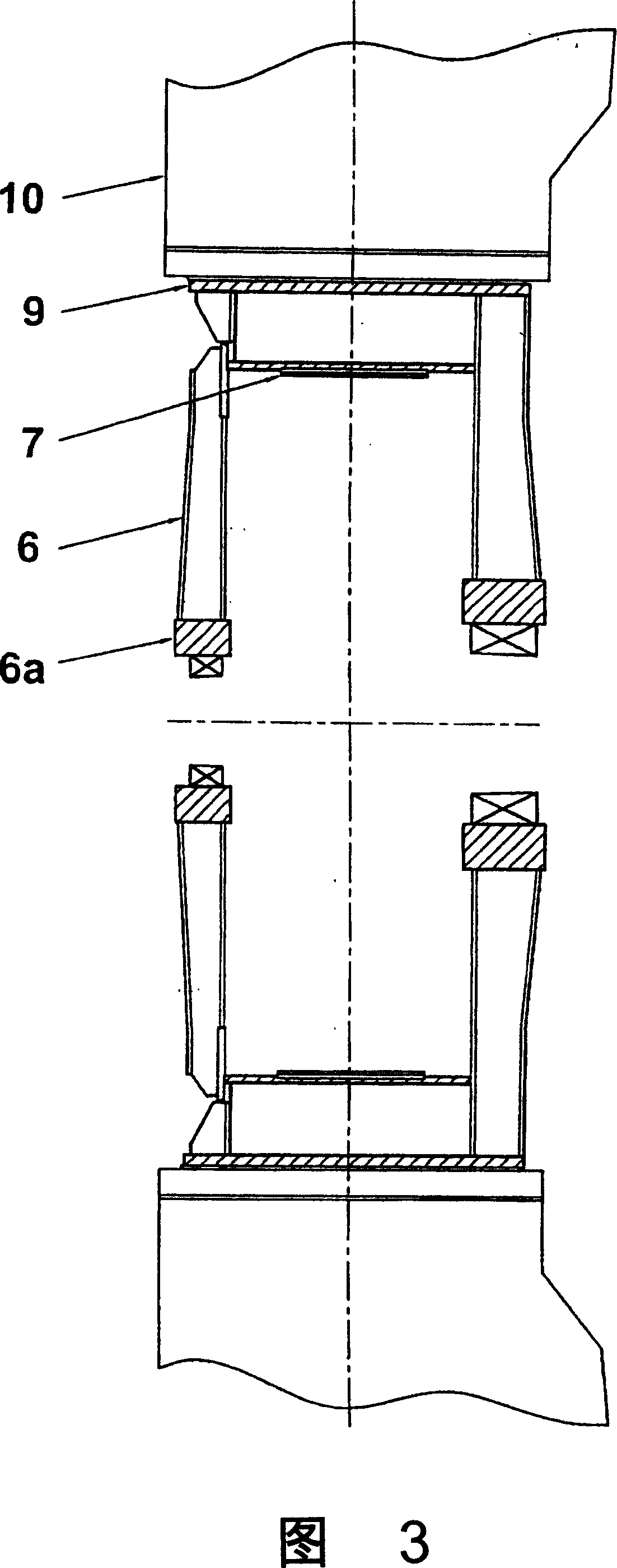
[0035] 1. Motor sensor element (Figure 3).

[0036] 2. Sensing structural elements (Fig. 2).

[0037] The motor inductor element (6) is formed by:

[0038] a) A mechanism element that converts the force driven by the blade (10) into torque.

[0039] b) Induction electrodes (07) for generating a magnetic field.

[0040] c) Roller bearings (6a) supporting the rotation of the assembly.

[0041] The sensing structural element (Fig. 2) is formed by:

[0042] a) Structural element (04) supporting the stator core and sensing coil.

[0043] b) Stator core (05) and sensing coil.

[0044] c) Structural element (03) on which the motor sensor element rotates.

[0045] The motor inductor element (6) consists of a circular band connected at...


PUM


Abstract

INTEGRATED WIND POWER GENERATOR. It is a device that integrates the functions of a wind turbine and a generator. In the main part of the induced structural component (4) are located the induction circuits, the core and the coil (5), and in the motor-inducer component (6), the blades supports (10) and the induction poles (7) are placed. When wind circulation occurs, the energy acting on the blades causes the motor-inducer component (6) to rotate around the induced structural component (3) generating a rotating magnetic field inducing an EMF in the induction circuits. According to what it is herein described, electricity is generated in the induction circuits (5) through only one device, functionally inseparable, in which both motor and generator functions are integrated.

Description

technical field [0001] The invention consists of an integrated wind power generator which combines the functions of a turbine and a generator in one device. Background technique [0002] Machines that convert the kinetic energy of wind into electricity are called "wind turbines". This type of machine can be further subdivided into two groups: low-power wind turbines and high-power or high-energy wind turbines. The former are low-performance devices that range in power from hundreds of watts to tens of kilowatts. Typically, they are lighter, less complex machines used to power less energy-intensive devices far from the grid. The latter are devices with sufficient power to be connected to the grid, which supply important energy-consuming centers. These machines range in power from hundreds of kilowatts to megawatts, and they differ considerably in their level of technical sophistication. In the energy conversion chain of any generator, two main stages can be distinguished...

Claims


Application Information

Patent Timeline
Patent Type & Authority Applications(China)
IPC IPC(8): F03D9/00H02K7/18H02K21/12H02K21/22
CPCH02K7/1838Y02E10/725F05B2220/7066Y02E10/722F03D9/002F03D11/00F05B2220/7068Y02E10/726H02K7/183F03D1/0658Y02E10/721F03D9/25F03D80/00Y02E10/72F03D80/70
Inventor E·帕斯卡蒙纳J·马那尼斯
Owner IND METALURGICAS PESCARMONA I C & F IMPSA
Learn More