
Tapered roller bearing

A technology of tapered rollers and bearings, applied in the field of tapered roller bearings, can solve problems such as adding cages, and achieve the effect of preventing surface starting wear and increasing load capacity

Active Publication Date: 2007-05-02
NTN CORP
View PDF1 Cites 10 Cited by
  • Summary
  • Abstract
  • Description
  • Claims
  • Application Information

AI Technical Summary

Problems solved by technology

For this, however, the pitch circle of the cage must be increased in order to pull the cage as far as possible to the outer ring

Method used


Image

  • Tapered roller bearing
  • Tapered roller bearing
  • Tapered roller bearing

Examples


Embodiment Construction

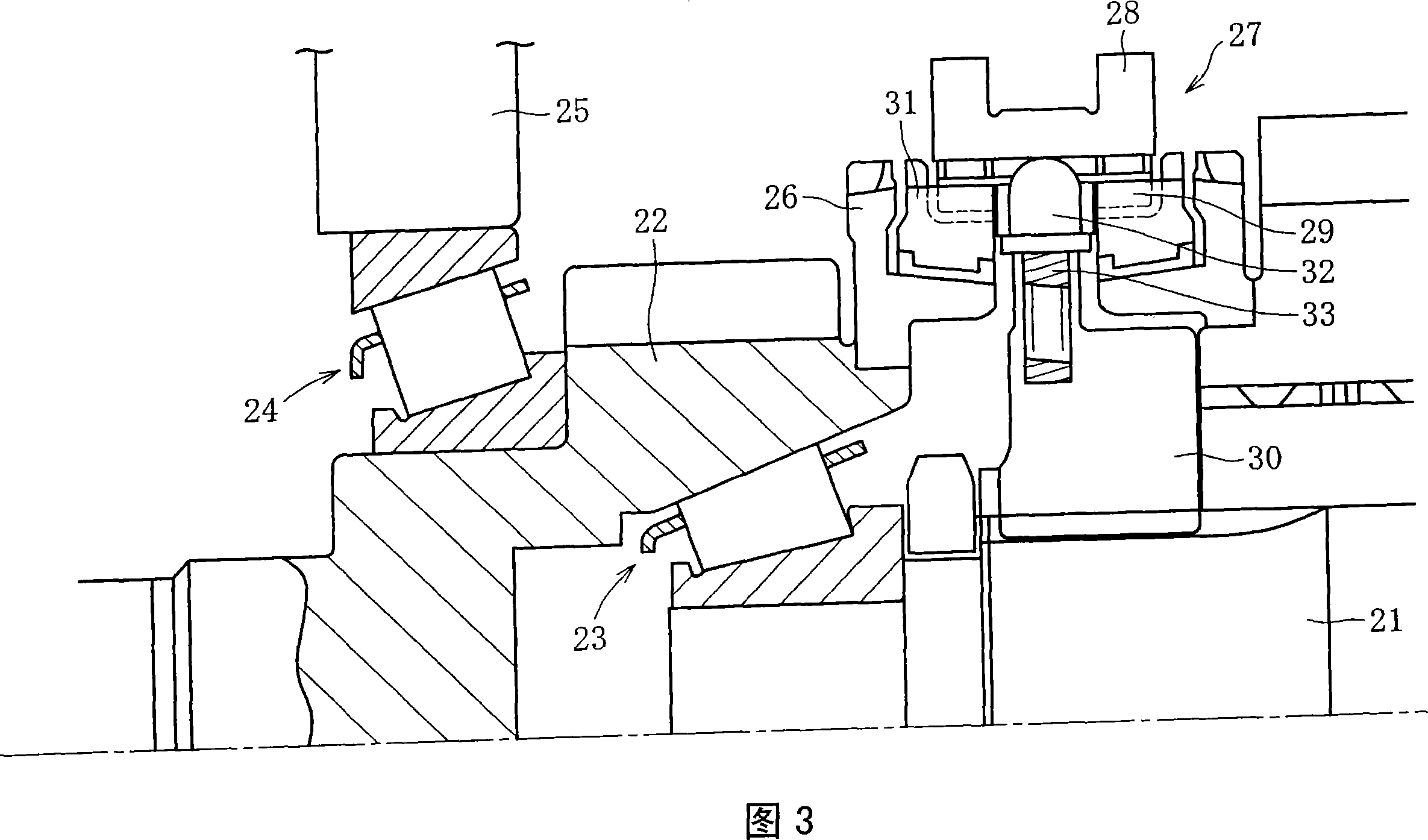
[0036] The transmission (main transmission unit) of an automobile is roughly classified into a manual type and an automatic type. In addition, they can also be classified according to the drive system of the vehicle: front-wheel drive (FWD) transmission differential, rear-wheel drive (RWD) gearbox and four-wheel drive (4WD) transfer case (auxiliary transmission unit ). They are used to shift the drive power from the engine and transmit it to the drive shaft, etc.

[0037]Fig. 3 shows an example of the structure of an automobile gearbox. This gearbox is of the synchromesh type, where in the same figure, the left side is the engine side and the right side is the drive wheel side. A tapered roller bearing 23 is inserted between the main shaft 21 and the main drive gear 22 . In this example, the inner periphery of the main drive gear 22 is directly formed with the outer ring raceway surface of the corresponding tapered roller bearing 23 . The main drive gear 22 is supported by...


PUM


Abstract

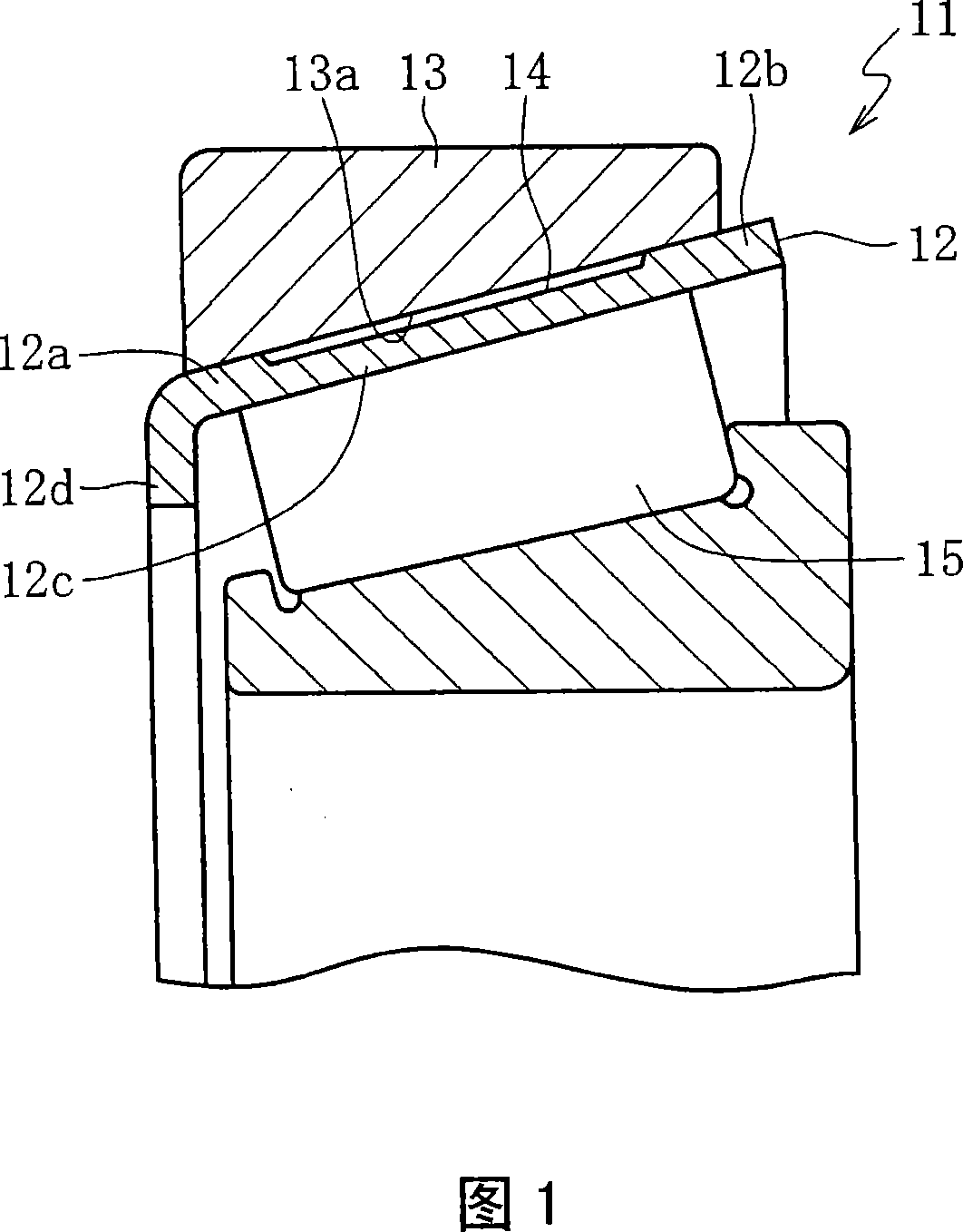
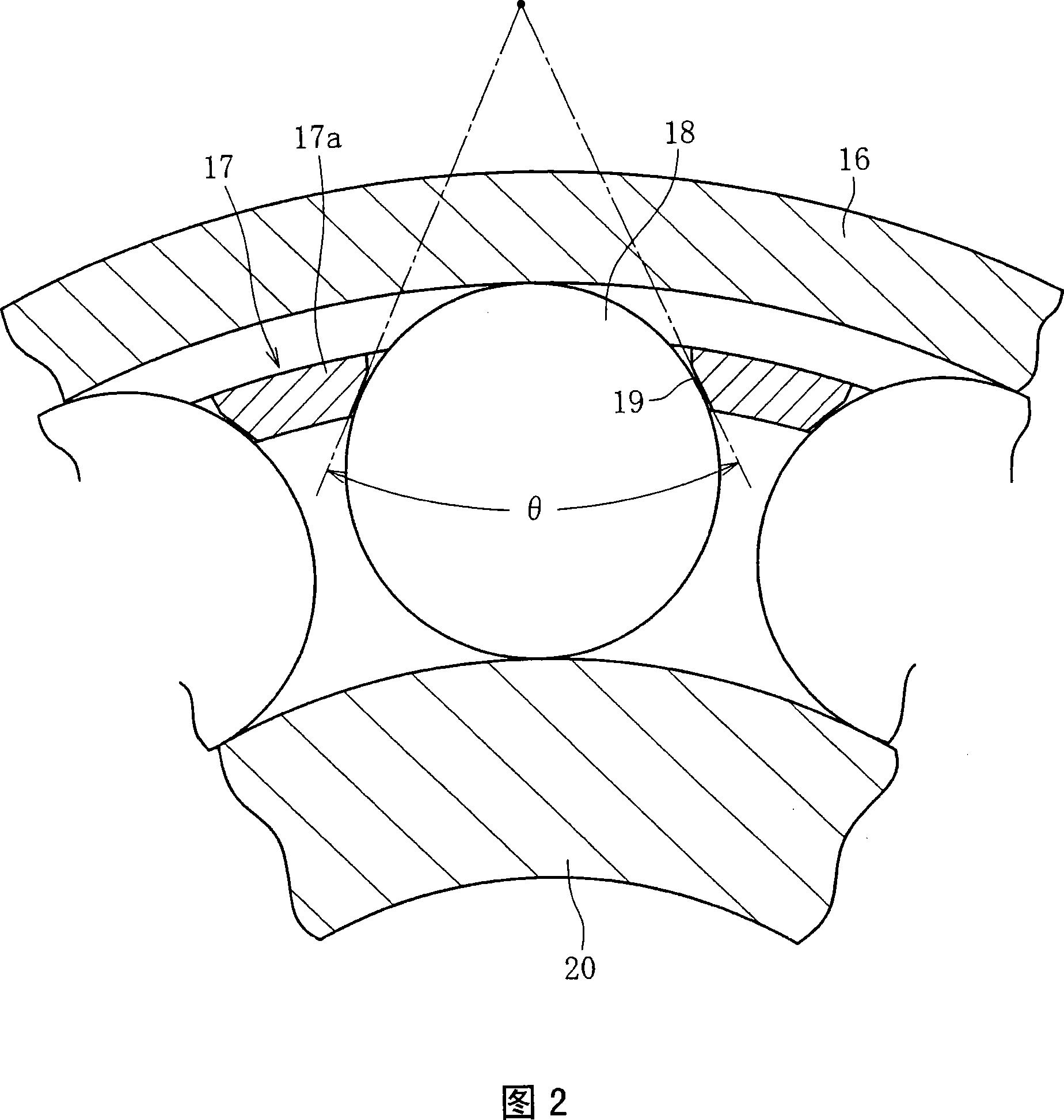
A tapered roller bearing (1) used in transmissions or differentials for automobiles includes an inner ring (2), an outer ring (3), a plurality of tapered rollers (4) rollably disposed between the inner and outer rings (2 and 3), and a cage (5) for holding the tapered rollers (4) at circumferential predetermined intervals, wherein the roller coefficient Gamma exceeds 0.94, where Gamma is (the number of rollers x mean roller diameter) / (Pi x PCD).

Description

technical field [0001] The present invention relates to tapered roller bearings, and more particularly, but not limited to, tapered roller bearings used in support gears of automotive transmissions or differentials. Background technique [0002] Automobile gearboxes tend to use low-viscosity oil recently to obtain AT, CVT, low fuel consumption, etc. of the gearbox. In environments where low-viscosity oils are used, surface start-up wear leading to very short bearing life sometimes occurs at the inner ring raceway surface with high surface pressure due to simultaneous occurrences such as (1) high oil temperature, (2) higher Poor lubrication under adverse conditions such as low oil quantity and (3) preload loss. [0003] As for the solution to this problem of short bearing life due to surface starting wear, the immediate and effective solution is to reduce the maximum surface pressure. In order to reduce the maximum surface pressure, it is necessary to change the bearing siz...

Claims


Application Information

Patent Timeline
IPC IPC(8): F16C33/46F16C19/36F16C33/56F16C33/58
Inventor 辻本崇
Owner NTN CORP
Learn More