Fibre-optical grating sensor and its wavelength demodulation method and sensor

A fiber grating and wavelength demodulation technology, which is applied in the direction of transmitting sensing components, optics, and instruments using optical devices, and can solve problems such as limiting the dynamic range of demodulation speed, low wavelength demodulation speed, and inability to adapt to high-speed dynamic signal measurement.

Inactive Publication Date: 2007-05-02
INST OF SEMICONDUCTORS - CHINESE ACAD OF SCI
View PDF0 Cites 18 Cited by
  • Summary
  • Abstract
  • Description
  • Claims
  • Application Information

AI Technical Summary

Problems solved by technology

Due to the need for a large number of mathematical calculations, the spectral analysis technology has a low wavelength demodulation speed and cannot adapt to the measurement of high-speed dynamic signals; the reliability and long-term stability of the wavelength scanning technology need to be further improved because of the existence of moving parts; Balanced M-Z interferometer demodulation technology is currently only applicable to the measurement of dynamic signals due to the problem of zero point drift
[0005] The traditional matched grating demodulation method uses an equal-period fiber Bragg grating, and its reflection spectrum bandwidth is usually not greater than 1nm. It is necessary to modulate the center wavelength of the reference fiber Bragg grating to realize wavelength scanning, which limits the demodulation speed and the measurable Dynamic Range

Method used


Image

  • Fibre-optical grating sensor and its wavelength demodulation method and sensor
  • Fibre-optical grating sensor and its wavelength demodulation method and sensor

Examples


Embodiment Construction

[0021] In order to more clearly introduce the purpose and advantages of the present invention, further description will be made below in conjunction with embodiments and accompanying drawings.

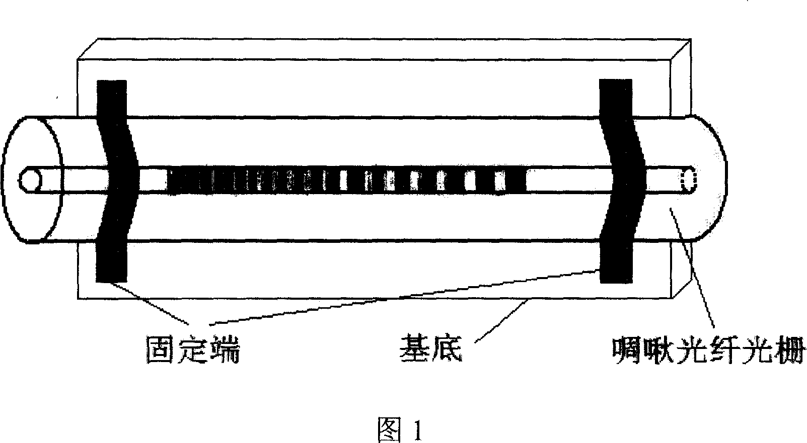
[0022] Figure 1 schematically shows the structural diagram of a chirped fiber grating sensor, and it can be seen that the period of the grid structure inside the fiber core changes continuously along the direction of the fiber core axis. Chirped fiber gratings can be directly exposed using a chirped mask, or can be realized by packaging equal-period fiber gratings with different intensity strains. The chirped fiber grating can be fixed on the base material by glue or welding.

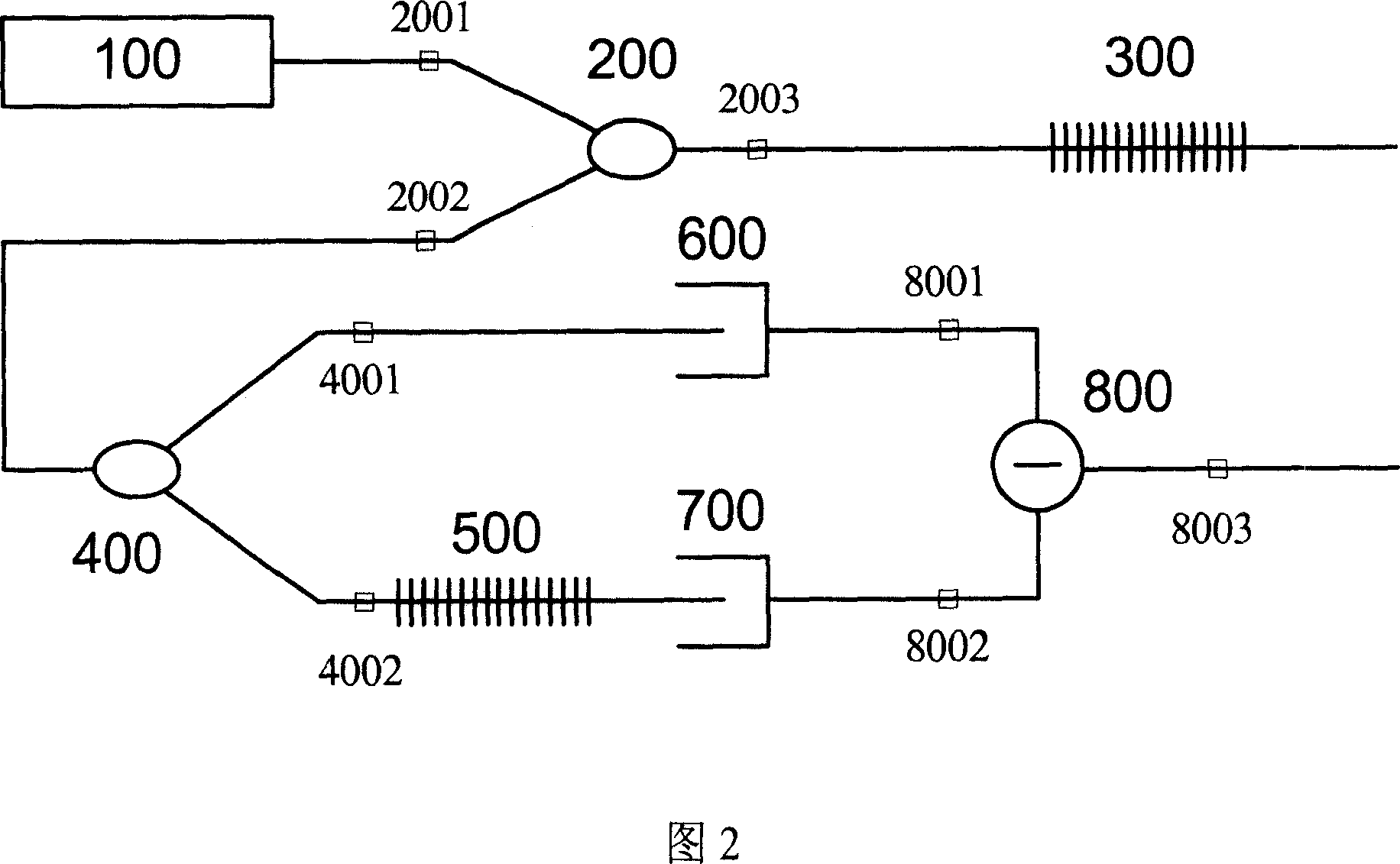
[0023] Fig. 2 schematically shows a scheme for realizing wavelength demodulation by using a reference chirped fiber grating. The output optical signal of the broadband light source 100 enters the fiber coupler 200 through the port 2001 , and enters the chirped fiber grating sensor 300 after exiting the port 200...


PUM


Abstract

A transducer of fiber optics grating is prepared as packaging chirp fiber optics grating, forming wavelength demodulation unit by one wideband optical source, two optical fiber couplers, two photoelectric detectors and one reference chirp fiber optics grating matching to transducer of fiber optics grating. The wavelength demodulating method utilizing said transducer is also disclosed.

Description

technical field [0001] The invention discloses a fiber grating sensor in a fiber grating sensing system and a wavelength demodulation method thereof, in particular a method for realizing fiber grating sensing and its wavelength demodulation by using a chirped fiber grating. Background technique [0002] Fiber Bragg grating can convert the change of external environment (such as stress, strain, vibration, temperature change, etc.) [0003] Compared with traditional electrical sensors, fiber grating sensors have significant advantages: anti-electromagnetic interference, can work normally in harsh environments; optical fiber transmission loss is small, and can be monitored at long distances; fiber gratings have stable performance and long service life; fiber gratings and Optical fiber has natural compatibility, small package size and compact structure. Due to the many advantages mentioned above, fiber grating sensing has been more and more widely used. [0004] A core problem...

Claims


Application Information

Patent Timeline
IPC IPC(8): G01D3/028G01D5/26G02F1/03
Inventor 张松伟刘育梁
Owner INST OF SEMICONDUCTORS - CHINESE ACAD OF SCI
Why Eureka
Try Eureka