
A flow field plate and fuel cell stack containing the same

A fuel cell stack and flow field plate technology, which is applied to fuel cells, fuel cell parts, battery electrodes, etc., can solve the problems of reactant diffusion, reaction product discharge, etc., and achieve short process, high utilization rate, effective The effect of spreading

Inactive Publication Date: 2007-04-25
BYD CO LTD
View PDF1 Cites 5 Cited by
  • Summary
  • Abstract
  • Description
  • Claims
  • Application Information

AI Technical Summary

Problems solved by technology

[0016] The purpose of the present invention is to provide a flow field plate that can distribute the reactants very evenly and discharge the reaction products in time, thereby effectively solving the problems of the diffusion of the reactants and the discharge of the reaction products

Method used


Image

  • A flow field plate and fuel cell stack containing the same
  • A flow field plate and fuel cell stack containing the same
  • A flow field plate and fuel cell stack containing the same

Examples


Embodiment Construction

[0025] The present invention will be further described below in conjunction with the accompanying drawings and specific embodiments.

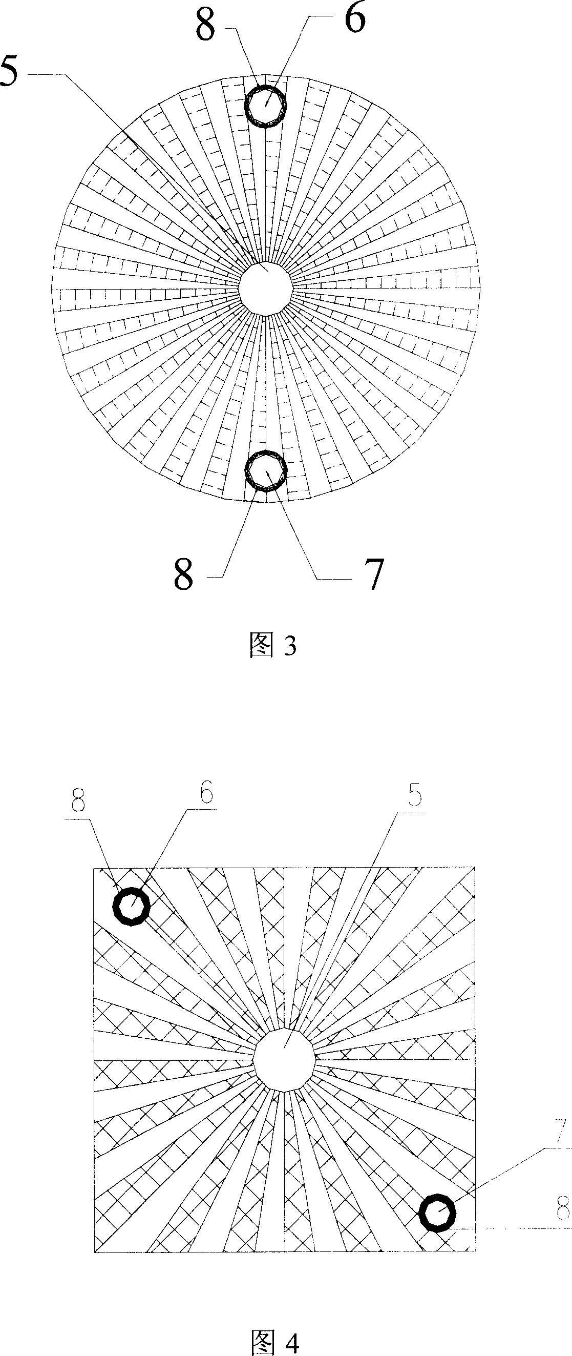
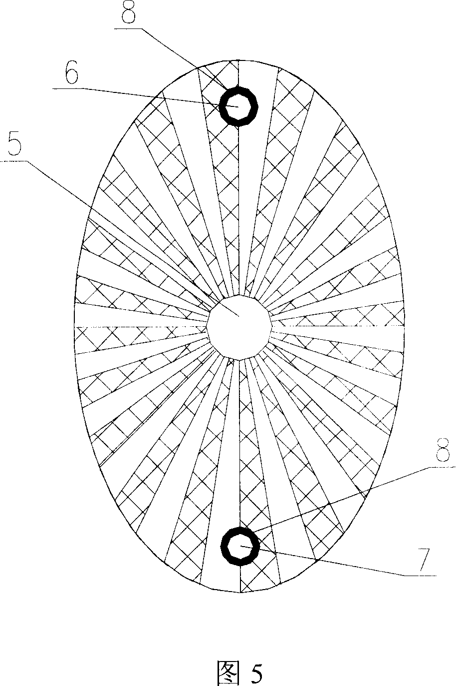
[0026] The flow field plate provided by the present invention includes a central hole 5 located at the center of the flow field plate, an inflow hole 6 and an outflow hole 7 located at two positions close to the edge of the flow field plate, preferably, the inflow hole 6 and the outflow hole 7 The position is symmetrical with respect to the central hole 5 . One side of the flow field plate includes flow guide grooves diverging from the central hole 5 to the surroundings.

[0027] Wherein, the flow field plate can be made of graphite or metal materials, such as titanium, stainless steel, gold, silver or copper, and other materials with good electrical conductivity. The flow field plate can be in various shapes, such as circular, elliptical or polygonal, preferably circular, rectangular or elliptical. The central hole 5, the inflow hole 6 and t...


PUM


Abstract

The invention relates to a flow field plate and relative fluid accumulator. Wherein, said flow field plate comprises a central hole at the middle of plate, an inlet and an outlet (6, 7) at two positions near the edge of plate; one surface of it comprises divert groove radiated from the central hole (5) to circumstance. Since the plate has radiated divert groove with short length, the reaction agent can be dispersed easily, to avoid dead area, to flow into any part of flow, and the generated material as water, nitrogen, etc, can be discharged on time, to improve the utilization of reaction agent.

Description

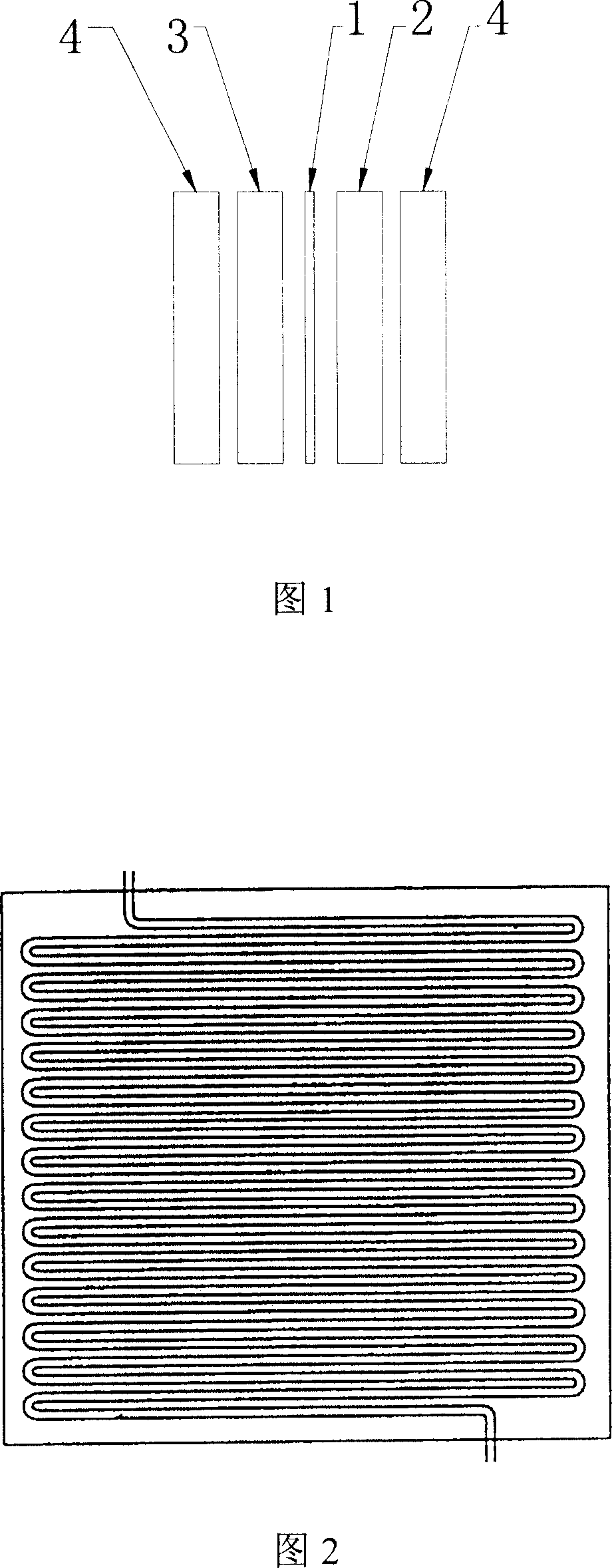
technical field [0001] The invention relates to the field of fuel cells, more specifically, to a flow field plate and a fuel cell stack including the flow field plate. Background technique [0002] A fuel cell is a power generation device that directly converts chemical energy in fuel and oxidant into electrical energy. It has the characteristics of high efficiency, less pollution and low noise. A fuel cell can be just a single fuel cell, or a fuel cell stack composed of multiple single fuel cells. [0003] A single fuel cell generally includes a proton exchange membrane 1 , an anode 2 , a cathode 3 and a guide plate 4 , as shown in FIG. 1 . [0004] The proton exchange membrane 1 is a water-permeable and air-tight semi-permeable membrane, which has the function of proton conduction and can also prevent mixed explosion of oxidant and fuel. [0005] Anode 2 is a gas diffusion electrode, and its supporting material is generally composed of conductive carbon fiber or carbon c...

Claims


Application Information

Patent Timeline
Patent Type & Authority Applications(China)
IPC IPC(8): H01M8/02H01M4/86H01M8/0202H01M8/0258
CPCY02E60/50
Inventor 董俊卿
Owner BYD CO LTD
Learn More