
Ball end mill

A ball-end mill and ball-end technology, used in milling cutters, cutters for milling machines, forming cutters, etc., can solve the problems of inability to cut, large cutting resistance, high-speed cutting, etc., to achieve processing efficiency and prevent sharpness. The effect of reducing the speed and improving the processing efficiency

Inactive Publication Date: 2007-04-04
OSG
View PDF1 Cites 10 Cited by
  • Summary
  • Abstract
  • Description
  • Claims
  • Application Information

AI Technical Summary

Problems solved by technology

[0005] However, in the above-mentioned ball nose end mill, the cutting edge is formed in a straight line when viewed in the axial direction, so the cutting resistance during cutting is large, and it is not possible to perform deep cutting or high-speed cutting.
Therefore, there is a problem that sufficient machining efficiency cannot be obtained in a structure in which a plate member having a double-layer structure is welded as a cutting edge to the corner portion of the ball end mill.

Method used


Image

  • Ball end mill
  • Ball end mill
  • Ball end mill

Examples


Embodiment Construction

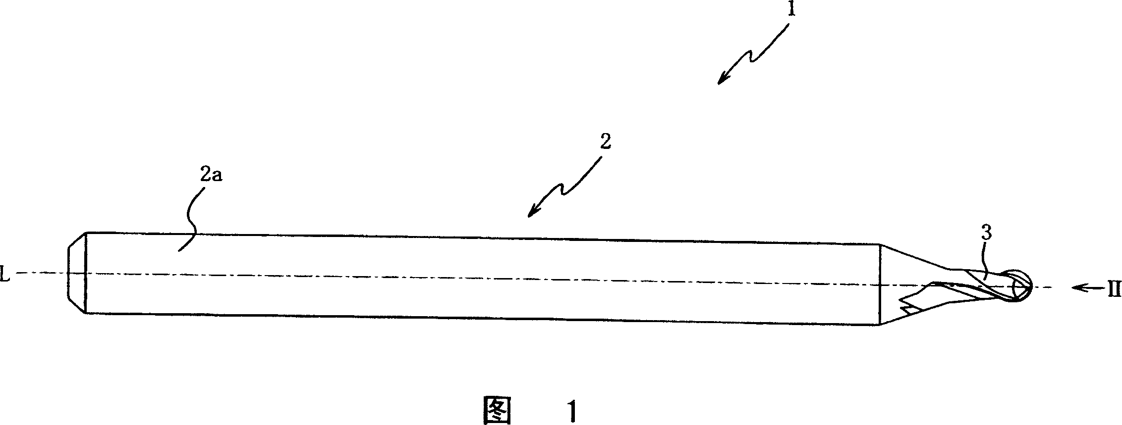
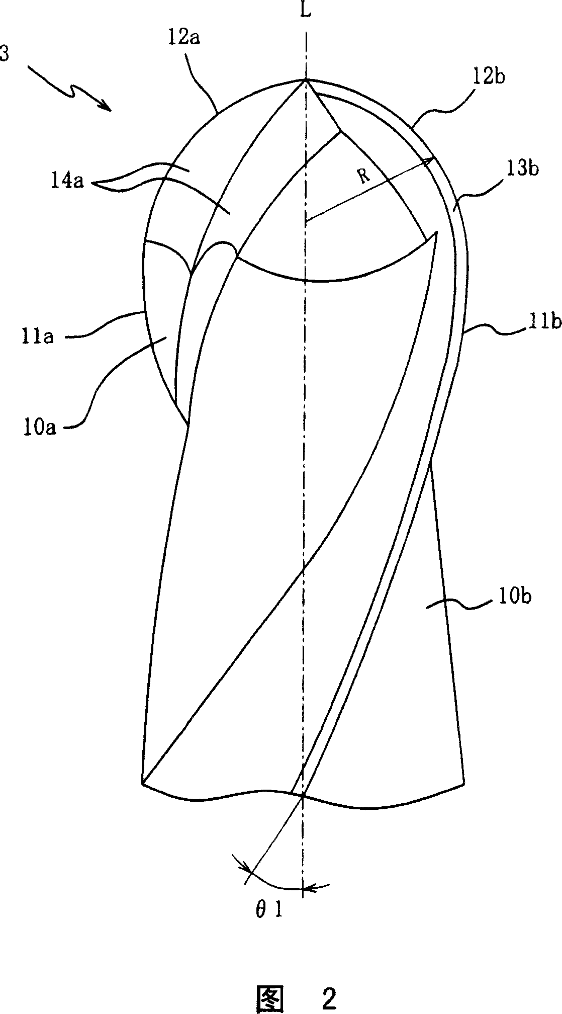
[0037] Hereinafter, preferred embodiments of the present invention will be described with reference to the accompanying drawings. Fig. 1 is a front view of a multi-flute ball end mill (hereinafter simply referred to as a ball end mill) 1 as an embodiment of the present invention, and Fig. 2 is a tip side of the ball end mill 1 (right side in Fig. 1 ). side), FIG. 3 is a side view of the ball end mill 1 viewed from the direction of arrow II in FIG. 1 . First, the overall structure of the ball end mill 1 will be described with reference to these FIGS. 1 to 3 .

[0038] The ball end mill 1 mainly includes: a tool body 2 having an axis L, and a cutting edge 3 coaxially connected to the end side of the tool body 2, and is used for free-form surface machining or Finishing of chamfering, etc. This ball end mill 1 is mounted on a processing machine such as a machining center via a holder (not shown) holding the shank portion 2a of the tool body 2, and is driven to rotate around the ...


PUM


Abstract

A ball end mill enabling an increase in machining efficiency, wherein a pair of roughly semi-spherical ball edges (12a) and (12b) are formed on an edge part (3) at the tip thereof symmetrically with respect to the axis thereof, and the area of the edge part (3) including at least the ball edges (12a) and (12b) is formed of a hard sintered body (PCBN). Also, the faces of the ball edges (12a) and (12b) are formed by spiral gashes (14a) and (14b), and the helix angles of the spiral gashes (14a) and (14b) are formed at approximately 20 DEG. Since the ball edges (12a) and (12b) are formed of the hard sintered body having high hardness characteristic and formed in a twisted shape, the ball end mill can cut with a large depth of cut and at high speeds to increase the machining efficiency of the ball end mill.

Description

technical field [0001] The present invention relates to a ball end mill, and more particularly, to a ball end mill capable of improving machining efficiency by constituting a cutting edge with a hard sintered body. Background technique [0002] In the profiling of molds and the like by machine tools such as machining centers, ball nose end mills made of cemented carbide are generally used, but when machining molds that have been quenched for longer life, The cutting edge of the ball nose end mill wears faster and the tool life is shortened. In addition, although the life of the ball end mill can be extended by making the depth of cut shallower, in this case, the machining time for performing predetermined machining increases, resulting in a corresponding decrease in machining efficiency. In view of this, in recent years, ball nose end mills using a sintered cubic boron nitride (PCBN) body having high hardness for the cutting edge have been adopted in order to reduce wear of...

Claims


Application Information

Patent Timeline
Patent Type & Authority Applications(China)
IPC IPC(8): B23C5/10
CPCB23C2226/315B23C5/1009Y10T407/1946B23C2210/03B23C2226/125B23C2210/0485B23C2210/0407B23C2222/28B23C2210/0435
Inventor 永井保
Owner OSG
Learn More