
Equalizer and equalizing method

An equalizer and equalization technology, which is applied in equalizers, shaping networks in transmitters/receivers, baseband system components, etc., can solve problems such as incorrect equalization, large errors, and inability to remove noise components, etc.

Inactive Publication Date: 2007-03-28
LAPIS SEMICON CO LTD
View PDF3 Cites 5 Cited by
  • Summary
  • Abstract
  • Description
  • Claims
  • Application Information

AI Technical Summary

Problems solved by technology

[0007] However, since the OFDM demodulation device of Patent Document 1 is based on the premise of receiving a signal having the frame structure as described above, there is a problem that the data structure in which pilot symbols are scattered among the data symbols used for terrestrial digital broadcasting cannot be demodulate the signal
However, the OFDM signal receiving device of Patent Document 2 passes only the inverse fast Fourier transformed signal through the LPF, and cannot remove the noise components contained in the region where the LPF passes in advance.
Therefore, the OFDM signal receiving device of Patent Document 2 has a problem that, as the noise included in the received signal increases, the error in the propagation path estimation result increases and the reception characteristic deteriorates.
However, Patent Document 3 does not use inverse Fourier transform, but relatively compares the pilot symbols of the same subcarrier existing in the fourth symbol before
Therefore, there is a problem that the change in the transfer function of the transmission path cannot be known until the pilot symbol of the same subcarrier that appears after 4 symbols appears, and it is easy to fail to perform equalization correctly when the transfer function of the transmission path changes within 4 symbols. Case

Method used


Image

  • Equalizer and equalizing method
  • Equalizer and equalizing method
  • Equalizer and equalizing method

Examples


Embodiment 1

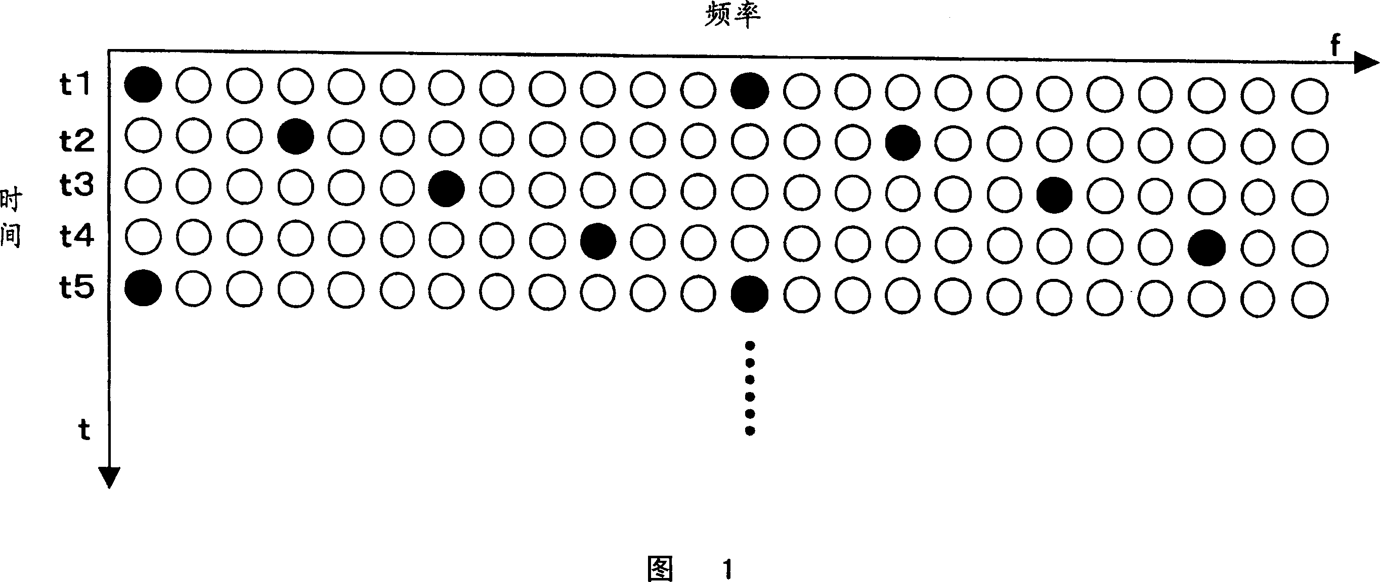
[0033] Next, the equalizer and equalization method of Embodiment 1 will be described. When using Fig. 1 to illustrate the concept of the equalizer and the equalization method of Embodiment 1, the equalizer and the equalization method of Embodiment 1 use the pilot symbols of the current (for example t3) OFDM symbol to decipher the current OFDM symbol Tune.

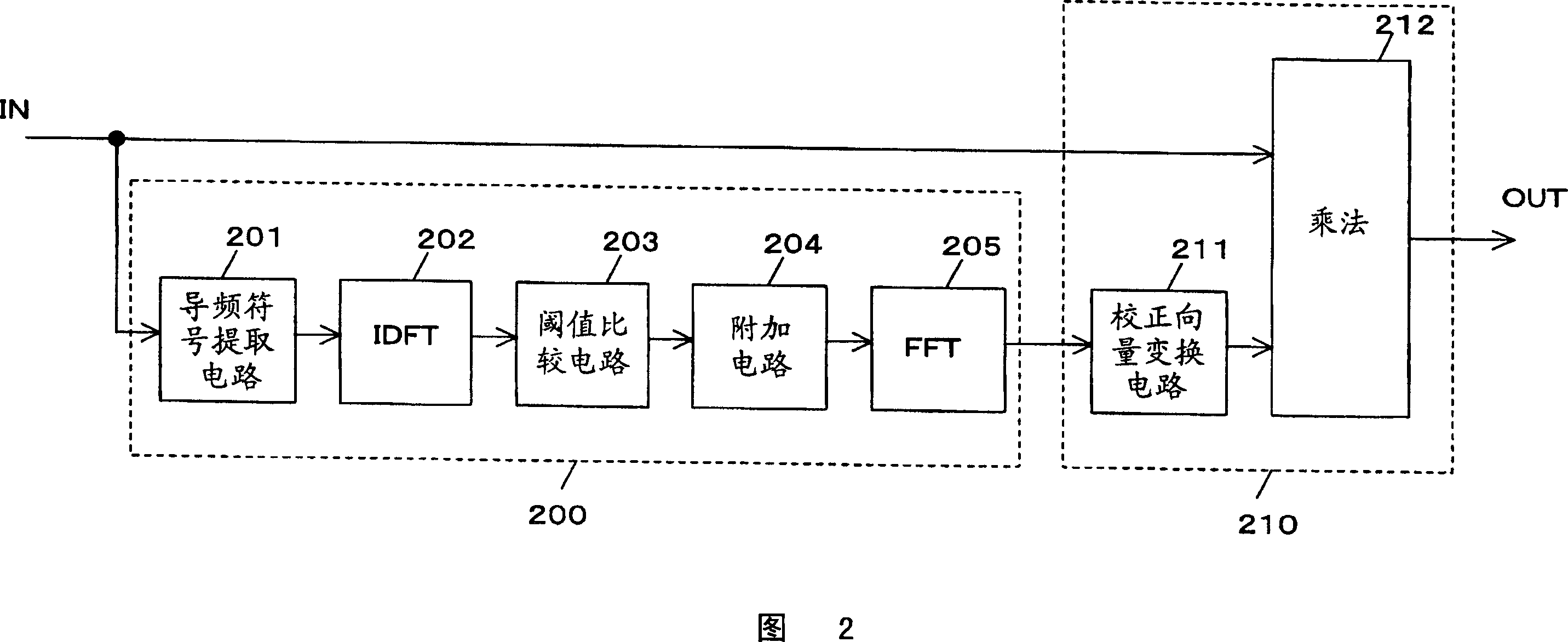
[0034] FIG. 2 is a block diagram showing the structure of the equalizer of the present invention. The equalizer of the present invention includes a channel estimation unit 200 and an equalization calculation unit 210 that receive a Fourier-transformed input signal IN. Here, the input signal is a signal subjected to Fourier transform in units of one OFDM symbol.

[0035] The channel estimation unit 200 includes a pilot symbol extraction circuit 201 , an inverse discrete Fourier transform circuit 202 , a threshold comparison circuit 203 , an addition circuit 204 , and a fast Fourier transform circuit 205 .

[0036] Pilot s...

Embodiment 2

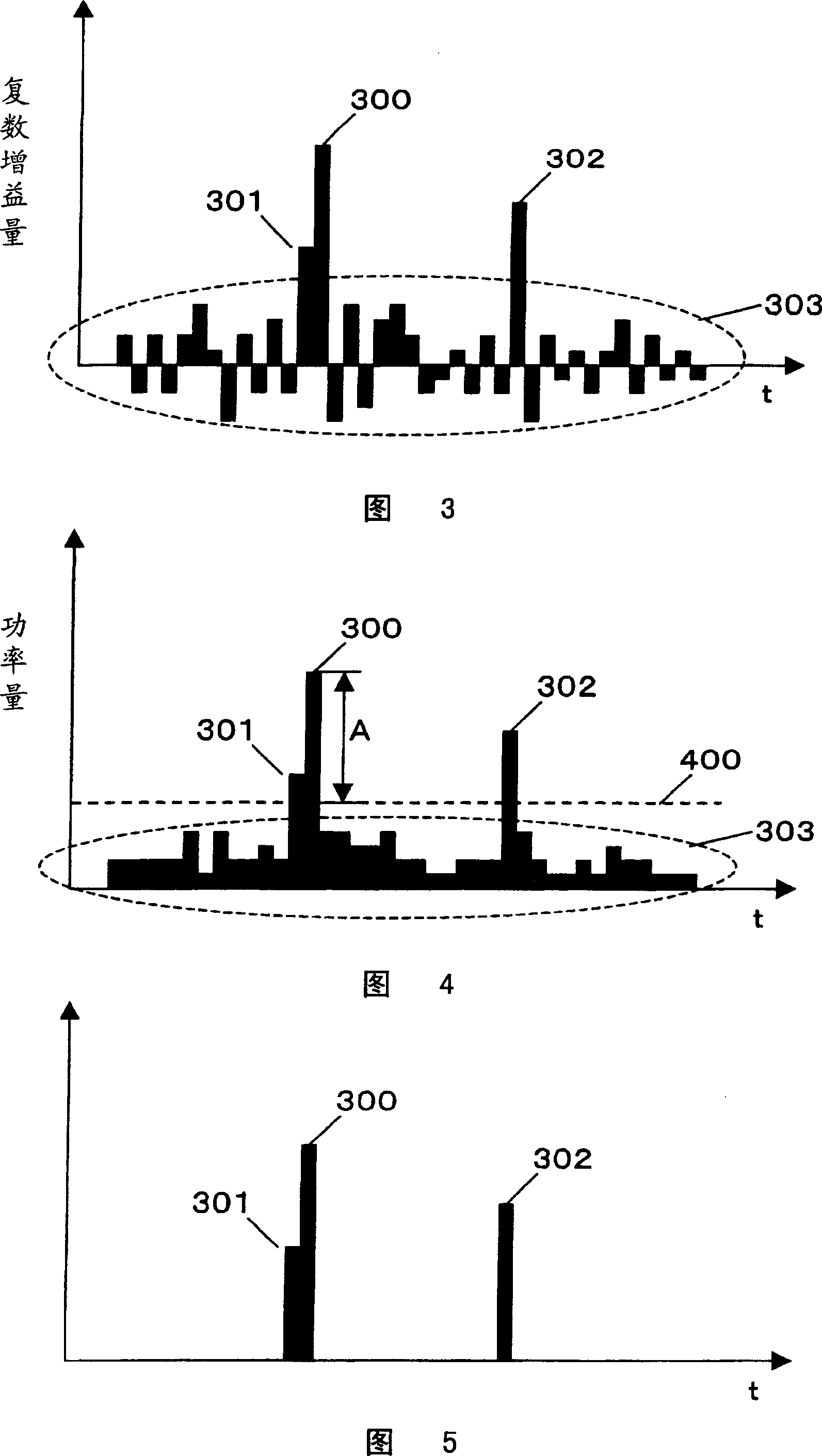
[0056] The path extraction method of the equalizer and the equalization method in the second embodiment are different from those in the first embodiment. In the threshold comparison circuit of the first embodiment, the path is extracted using the power amount obtained by squaring the complex gain amount. On the other hand, in the threshold comparison circuit of Embodiment 2, paths are extracted using the absolute values ​​of the real and imaginary numbers of the complex gain amount.

[0057] Specifically, the threshold comparison circuit of the second embodiment obtains the absolute value of the real number and the imaginary number of the complex gain amount of each path obtained in the discrete Fourier inverse transform circuit 202, and adds the absolute values ​​of the real number and the imaginary number for each path. operation. The threshold comparison circuit extracts a path having the largest complex gain amount as a result of addition. Then, the threshold comparison ...

Embodiment 3

[0063] The method of transforming the correction vector of the equalizer and the equalization method of the third embodiment is different from the first and second embodiments. The correction vector conversion circuits of Embodiments 1 and 2 extract only the phase components corresponding to the channel estimates of the respective subcarriers. On the other hand, the correction vector conversion circuit of Embodiment 3 extracts the phase component and the amplitude.

[0064] More specifically, the correction vector conversion circuit of the third embodiment generates a correction vector that is the reciprocal of each subcarrier using the following formula.

[0065] (Formula 5)

[0066] SubC _ T = Re [ SubC ] - jIm [ SubC ] Re [ ...


PUM


Abstract

Provided are an equalizer and an equalization method. There is provided an equalizer that includes: a first extracting circuit extracting a plurality of pilot symbols from an inputted signal; an inverse Fourier transform circuit inversely Fourier transforming the extracted plurality of pilot symbols, and computing a complex gain per path; a second extracting circuit extracting a plurality of paths by using the complex gains; a Fourier transform circuit Fourier transforming the extracted paths; and an equalization computing circuit extracting phase components of the Fourier-transformed paths, and carrying out multiplication by using the inputted signal and the extracted phase components.

Description

technical field [0001] The present invention relates to the demodulation of OFDM (Orthogonal Frequency Division Multiplexing: Orthogonal Frequency Division Multiplexing) digitally modulated signal, and particularly relates to an equalizer (equalizer) and an equalization method using pilot symbols (pilot symbols). Background technique [0002] In terrestrial digital broadcasting (ISDB-T), the OFDM digital modulation method with strong anti-multipath interference is adopted. In order to demodulate a signal modulated by the OFDM modulation method (hereinafter referred to as OFDM signal), there is a scattered pilot (scattered pilot) that disperses pilot symbols in the frequency direction and time direction as the amplitude and phase reference for demodulation. Way. [0003] Patent Document 1 discloses an OFDM demodulation device, in particular, an automatic equalizer that performs inverse Fourier transform in order to perform equalization processing for removing channel distort...

Claims


Application Information

Patent Timeline
Patent Type & Authority Applications(China)
IPC IPC(8): H04L27/01H04L25/03H04L27/26
Inventor 赤堀博次
Owner LAPIS SEMICON CO LTD
Learn More