
Stage device

一种载物台、基座的技术,应用在机电装置、测量装置、采用光学装置等方向,能够解决构造受制约、成本高、移动物体检测装置制约等问题,达到降低制造成本、减轻装置重量的效果

Inactive Publication Date: 2007-03-21
SUMITOMO HEAVY IND LTD
View PDF1 Cites 13 Cited by
  • Summary
  • Abstract
  • Description
  • Claims
  • Application Information

AI Technical Summary

Problems solved by technology

That is, measuring devices such as rotary encoders and linear encoders used in conventional position measuring devices can only be used for one-dimensional positioning. For two-dimensional positioning, at least two of the above-mentioned measuring devices need to be combined. There are major constraints in the design
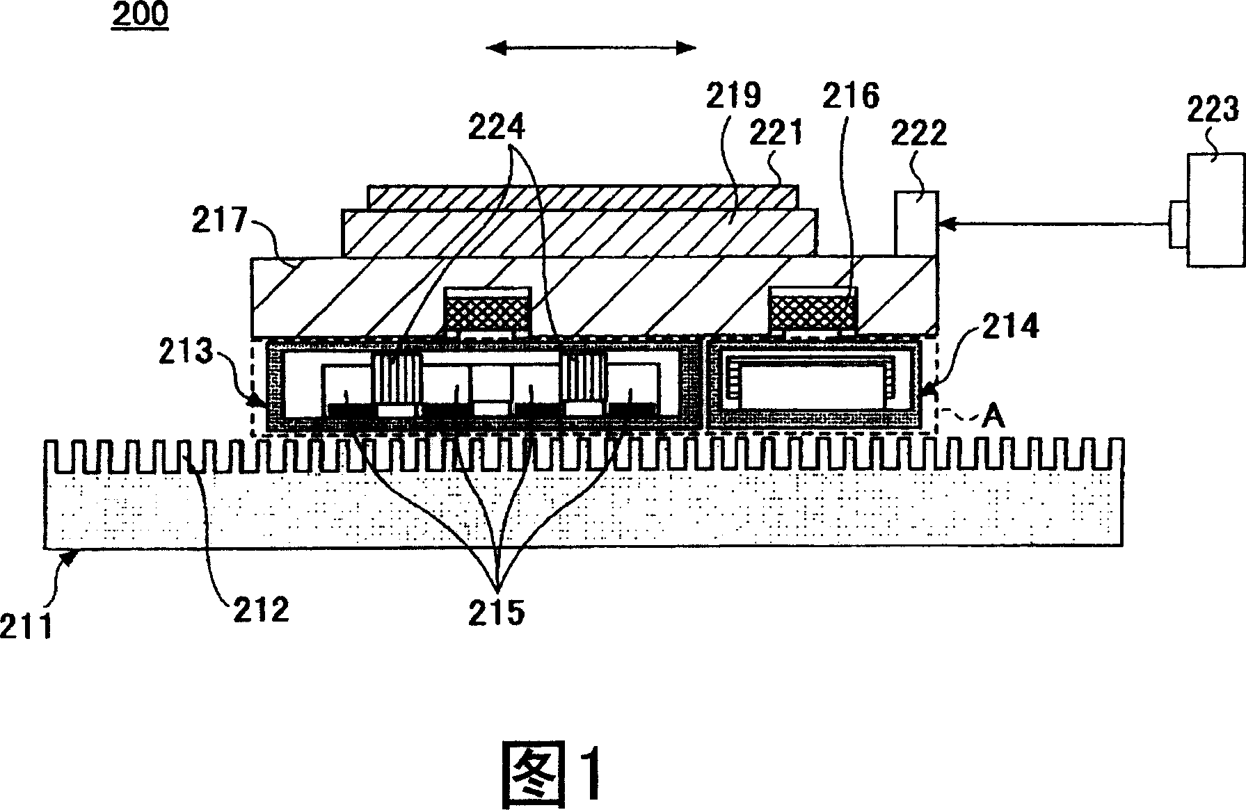
[0016] In addition, when using the laser interferometer 223 for positioning, essentially it can only perform one-dimensional positioning on one axis. When performing two-dimensional positioning, a high-precision long straight gauge is required.
As a result, when such a position measuring device is installed on the stage, there are problems of structural constraints and high cost.

Method used


Image

  • Stage device
  • Stage device
  • Stage device

Examples


no. 1 Embodiment

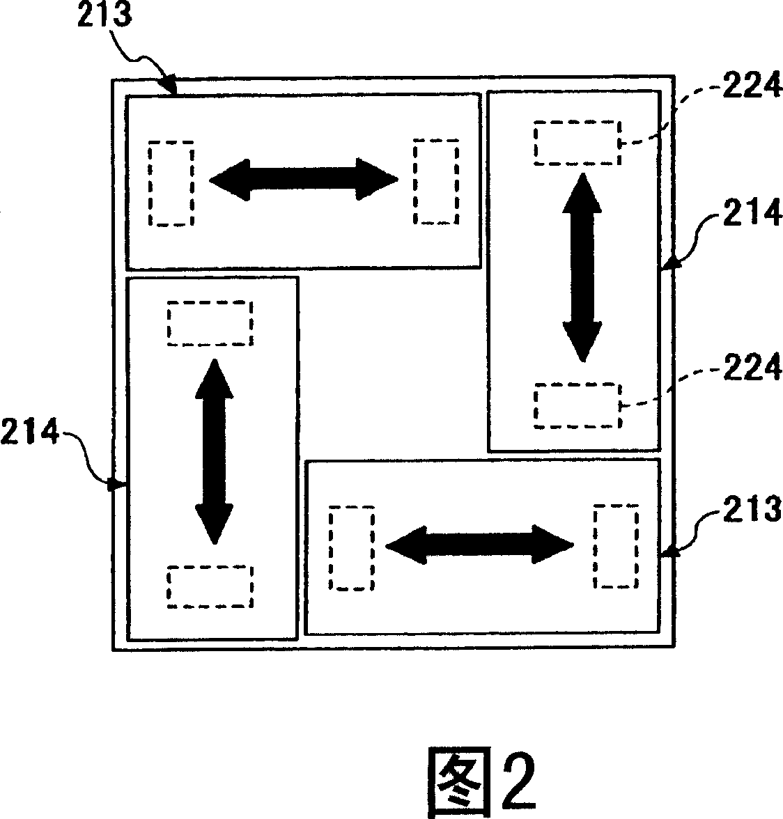
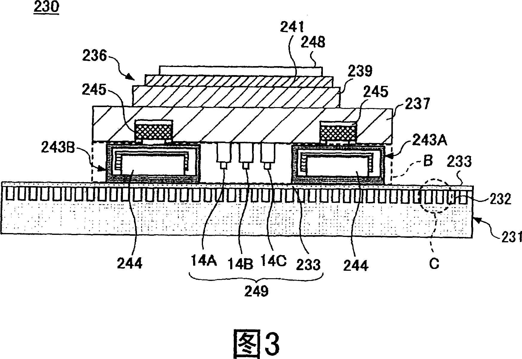
[0092] First, referring to FIG. 3 and FIG. 4 , the stage device 230 according to the first embodiment of the present invention will be described. 3 is a sectional view of the stage device of the first embodiment, and FIG. 4 is a plan view of the stage device corresponding to the area A shown in FIG. 3 .

[0093] The stage device 230 is a device having a SAWYER motor drive unit. Referring to FIG. 3 , the stage device 230 is composed of a base 231 , a stage 236 , and a surface encoder 249 . A plurality of protrusions 232 are formed at a predetermined pitch on the surface of the base 231 . This predetermined pitch becomes the minimum unit when movable stage 237 moves. In addition, the base 231 is made of metal such as iron. Stage 236 is composed of movable stage portion 237 , fixed stage portion 239 , jig 241 , X-direction actuators 242A, 242B, Y-direction actuators 243A, 243B, and tilt drive portion 245 .

[0094] The movable stage portion 237 is a base portion driven by X-d...

no. 2 Embodiment

[0129] Referring to FIG. 10 and FIG. 11, a stage device 10 as a second embodiment of the present invention will be described. FIG. 10 is an exploded perspective view of a stage device 10 according to a second embodiment of the present invention, and FIG. 11 is a perspective view of a partially cutaway assembled state of the stage device 10 . The stage device 10 is used for moving a wafer to be moved to a predetermined position in, for example, a stepper for semiconductor manufacturing.

[0130] The stage device 10 is composed of a base 11, a stage 12, a surface encoder 24, a driving device, and the like. The base 11 is a base of the stage device 10, and is provided with linear motor structure parts 20A and 25A, a Z-direction electromagnet 30, two-dimensional angle sensors 14A to 14C, etc. which will be described later. In addition, in this embodiment, the case of using the two-dimensional angle sensors 14A to 14C employed in the first embodiment will be described as an exampl...


PUM


Abstract

A stage device moving at a high accuracy in an X-Y direction and a rotating direction by a planar motor. The sizes of the stage device are reduced and measurement of a stage position to a base can be highly accurately performed. The stage device is provided with a scale unit (233), which is provided with a scale part, on the entire plane on the base (231), and three two-dimensional angle sensors (14A-14C) on a bottom plane part of a driving stage part (237). A surface encoder (249) is composed of the scale unit (233) and the two dimensional angle sensors (14A-14C), and a position of the driving stage (237) is measured by the surface encoder (249).

Description

technical field [0001] The invention relates to an object stage device, in particular to an object stage device which can move with high precision relative to the X-Y direction and the rotation direction through a planar motor. Background technique [0002] In semiconductor devices, ultra-precision machining devices, and the like, which are the basis of information technology, there are high demands for high precision, high speed, and the like of stage devices used in these devices. For example, a stage device, which is a key component of a semiconductor exposure device, needs to have an accuracy of about 10 nm and a movement range of several hundred mm. In addition, in order to improve the productivity of semiconductor devices, it is necessary to move the stage on which the workpiece is mounted to the processing position at high speed. Therefore, it is desired to have a stage device that satisfies all the above-mentioned requirements. [0003] For example, in various semi...

Claims


Application Information

Patent Timeline
Patent Type & Authority Applications(China)
IPC IPC(8): G01B11/00G01B11/26H01L21/027G03F7/20H01L21/68H02K41/03
CPCG03F7/70775G03F7/70716H01L21/68
Inventor 高伟清野慧富田良辛田野诚
Owner SUMITOMO HEAVY IND LTD
Learn More