
Support

A component and body technology, applied in the direction of shock absorber, shock absorber, non-rotational vibration suppression, etc., can solve the problem of preventing abnormal sound, achieve the effect of preventing abnormal sound and improving the effect of preventing abnormal sound

Inactive Publication Date: 2007-03-21
TOYO TIRE & RUBBER CO LTD +1
View PDF1 Cites 12 Cited by
  • Summary
  • Abstract
  • Description
  • Claims
  • Application Information

AI Technical Summary

Problems solved by technology

In order to prevent such abnormal noise, it is conceivable, for example, to make the contact surface between the stopper rubber part and the vehicle body a rough surface composed of fine unevenness such as wrinkles. The effect of preventing knocking noise can be expected at the time of contact, but the effect of preventing the abnormal sound cannot be fully exerted for the contact at the time of twisting when the above-mentioned force acts such as oblique contact and lateral displacement after contact.

Method used


Image

  • Support
  • Support
  • Support

Examples


no. 1 Embodiment

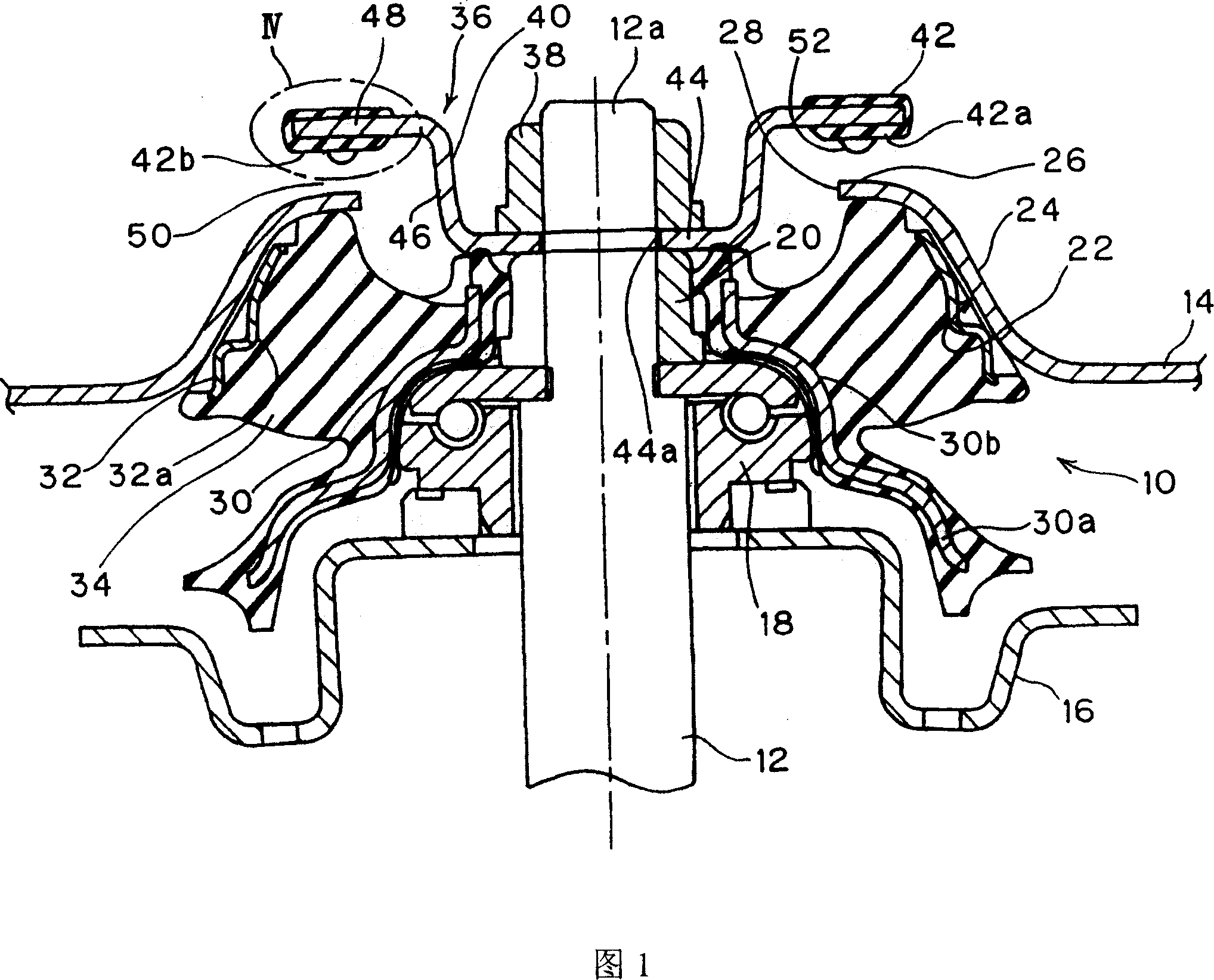
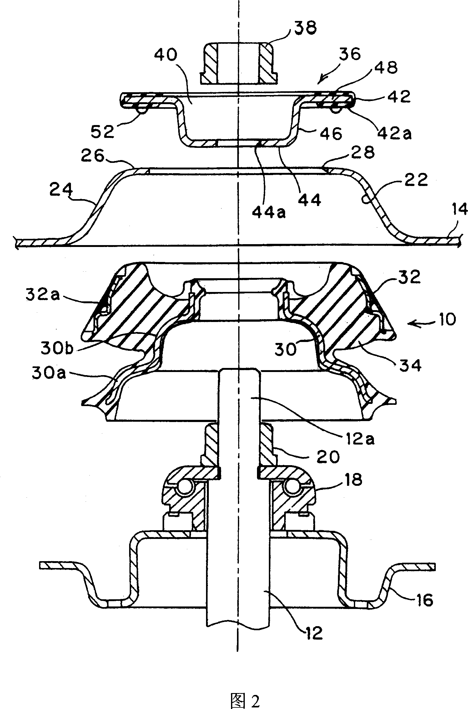
[0055] FIG. 1 is a sectional view showing a state in which a bracket 10 according to a first embodiment of the present invention is mounted on a vehicle, and FIG. 2 is an exploded view thereof.

[0056] In the figure, 12 is a piston rod of a shock absorber, 14 is a vehicle body, 16 is a spring seat supporting the upper end of the coil spring, and 18 is a bearing fixed to the upper end 12a of the piston rod by a nut 20 .

[0057] In the plate-shaped vehicle body 14, there is provided a recess 22 that is recessed upward and opened downward in a convex shape. The side wall portion 24 of the recess 22 is formed in a conical cylindrical shape whose diameter becomes smaller as it goes upward, and a circular opening portion 28 is provided in the upper wall portion 26 . The upper wall portion 26 extends radially inward from the upper end of the side wall portion 24, and is formed in the shape of a ring plate by providing an opening 28 inside, and the upper end portion 12a of the pisto...

no. 2 Embodiment

[0075] Next, a bracket 10A of a second embodiment will be described with reference to FIGS. 6 to 10 . The structure of the stopper rubber part 42 of the second embodiment is different from that of the above-mentioned first embodiment. The structure other than the stopper rubber part is the same as that of the first embodiment, and the same symbols are assigned to the same parts, and the description thereof will be omitted.

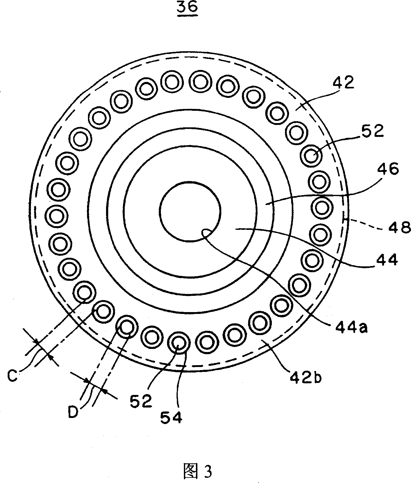
[0076] As shown in Figures 6 to 8, in this embodiment, on the lower surface 42b of the stopper rubber part 42, the plurality of spherical crown protrusions 52 are arranged at equal intervals along the entire circumference of the lower surface 42b to form a double inner and outer structure. ring. Further, the spherical crown protrusions 52 are arranged in an inner circular annular row 56 and an outer circular annular row 58 which are different from each other in the circumferential direction. That is, in the inner annular row 56 and the outer annular row ...


PUM


Abstract

A support is embedded into a concave part (22) of a vehicle body (14) from bottom of the vehicle body. The support is mounted as sandwiching between the vehicle body (14) and a piston rod (12) by use of the vehicle load but is not fastened on the support. The support comprises: an inner side component(3); an out side component (32); an anti-vibration basal body (34) which is made of rubber elastomer for combination of the components; and a support springback stopper (36) arranged on a top end (12a) of the piston rod for restricting downwardly relative displacement of the piston rod. A stop rubber part (42) is arranged on a stop plate part (48) of the support springback stopper, the stop plate part is opposed to, with a space thereof, a top wall part (26) around an open part (28) of the concave part (22). A plurality of spherical cap protuberance (52) are arranged along circumferential direction of a bottom surface of the stop rubber part (42). This invention can prevent noise generated when a rebound stopper and a body are brought into contact with each other in undesirable deformation displacement of a piston rod in a strut mount.

Description

technical field [0001] The present invention relates to a brace used in a strut suspension of a vehicle. Background technique [0002] The brace is a kind of anti-vibration device interposed between the upper end of the piston rod of the shock absorber and the body of the vehicle in the strut suspension of the automobile to attenuate or reduce the vibration transmitted from the road to the body. [0003] As such a brace, Japanese Patent Application Laid-Open No. 2004-232824 proposes a structure in which it is attached to the vehicle body in a non-connected state. That is, this document discloses such a bracket: it has a rigid inner member and an outer member, and a rubber elastic body that connects the inner member and the outer member as a whole, and is inserted into a recess for insertion provided in the vehicle body from the bottom up. In this place, it is not bolted to the vehicle body, but is installed on the vehicle body in a state of contac...

Claims


Application Information

Patent Timeline
Patent Type & Authority Applications(China)
IPC IPC(8): F16F9/54F16F15/08
Inventor 儿玉阳成土居司西部建志桂正治野野村真人
Owner TOYO TIRE & RUBBER CO LTD
Learn More