
Multifunctional transformer framework

A transformer skeleton and multi-functional technology, applied in the field of transformers, can solve problems such as inconvenience of use, hidden dangers of transformer safety, short circuit of coils, etc., and achieve the effects of accelerating heat dissipation, reducing danger, and avoiding coil contact.

Pending Publication Date: 2022-07-29
天长市瑞荣塑业有限公司
View PDF0 Cites 0 Cited by
  • Summary
  • Abstract
  • Description
  • Claims
  • Application Information

AI Technical Summary

Problems solved by technology

Transformer bobbins have various functions and different shapes according to requirements. There are disadvantages: First, the common bobbins are stored inside the transformer box. The second is that the iron core, coil and metal pins on the skeleton work independently. There is no blocking structure in the middle of the ordinary skeleton coil, and the electric terminals of the coil touch each other or touch the metal, which will cause a short circuit, which has a certain dangerous and inconvenient to use

Method used


Image

  • Multifunctional transformer framework
  • Multifunctional transformer framework
  • Multifunctional transformer framework

Examples


Embodiment 1

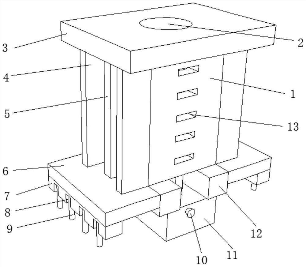
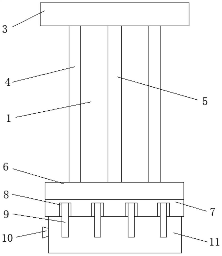
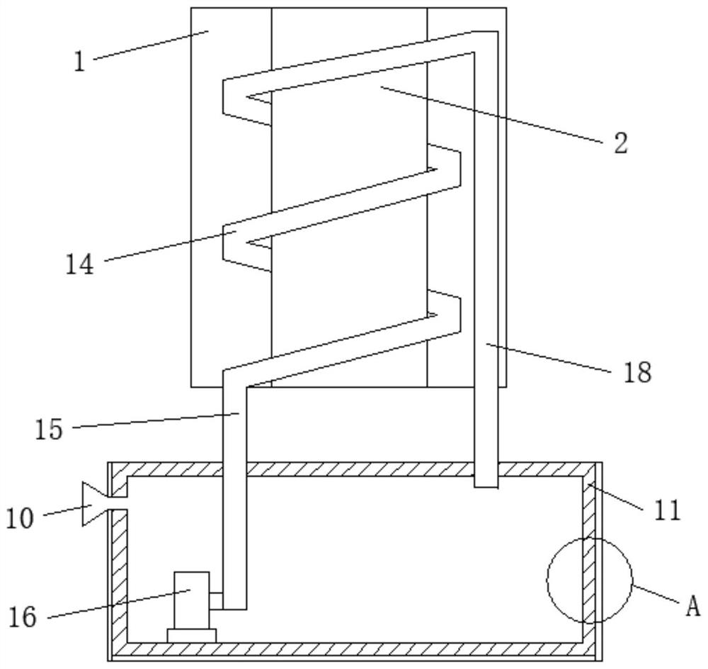
[0036] refer to Figure 1-4 , the present invention provides a multi-functional transformer skeleton, including a central column 1, the middle of the central column 1 is provided with a port 2, the left and right sides of the bottom end of the central column 1 are fixedly connected to the top of the beam frame 12, and the bottom of the beam frame 12 is fixedly connected. The ends are fixedly connected to the top of the water tank 11 , the inner wall of the bottom end of the water tank 11 is fixedly connected with a water pump 16 , the output end of the water pump 16 is fixedly connected to one end of the water inlet pipe 15 , and the other end of the water inlet pipe 15 is fixedly connected to one end of the annular pipe 14 . , the other end of the annular pipe 14 is fixedly connected to the top of the water outlet pipe 18, and the outer wall of the water tank 11 is provided with thermally conductive silica gel 17.

[0037] When the transformer is working, the coil is energize...

Embodiment 2

[0040] refer to Figure 1-4 , in the multifunctional transformer skeleton provided by the present invention, the top of the central column 1 is fixedly connected with a top plate 3, which plays a role of shielding, the through port 2 runs through the middle of the top plate 3, and the top middle of the bottom plate 6 is fixedly connected to the winding column 5. The bottom end, the top of the winding column 5 is fixedly connected with the top plate 3, the top of the baffle 4 is fixedly connected to the bottom end of the top plate 3, the baffle 4 surrounds the winding column 5 on the inside, the left and right sides of the center column 1 Baffles 4 are fixedly connected to the front and rear of the winding column 5, and baffles 4 are provided at the front and rear ends of the winding column 5 to isolate the coil wound on the surface of the winding column 5 in the interior, so as to achieve the purpose of isolating the coil and avoid the contact of the coil. Phenomenon.

Embodiment 3

[0042] refer to Figure 1-4 In the multifunctional transformer skeleton provided by the present invention, the top of the groove 8 is fixedly connected with a metal needle 9, the length of the metal needle 9 is greater than the length of the needle seat 7, and the metal needle 9 is arranged in the groove 8 to avoid contact with the coil. Contact, the annular pipe 14 is arranged inside the central column 1, the annular pipe 14 surrounds the outer circumference of the port 2, and the efficiency of heat dissipation is increased. Cooling liquid is added in the water tank 11 , and the front end of the center column 1 is evenly distributed with heat dissipation holes 13 , and the heat dissipation holes 13 all penetrate the center column 1 to achieve the effect of heat dissipation by air flow.

[0043]Working principle: When the transformer is working, the coil is energized to dissipate heat, and the water pump 16 transports the cooling liquid to the water inlet pipe 15, from the wat...


PUM


Abstract

The invention relates to the technical field of transformers, and discloses a multifunctional transformer framework which comprises a center column, a through opening is formed in the middle of the center column, a water pump is fixedly connected to the inner wall of the bottom end of a water tank, the output end of the water pump is fixedly connected to one end of a water inlet pipe, and the other end of the water inlet pipe is fixedly connected to one end of an annular pipeline. The other end of the annular pipeline is fixedly connected to the top end of the water outlet pipe, heat conduction silica gel is arranged on the outer wall of the water tank, the top ends of the bottom plates are fixedly connected to the bottom end of a baffle, and grooves are evenly distributed in the bottom end of the needle base. According to the cooling device, the water pump conveys cooling liquid to the water inlet pipe, absorbs heat in the flowing process of the annular pipeline and then flows into the water tank through the water outlet pipe, the heat absorbed by the cooling liquid is transmitted to the water tank, the surface of the water tank is coated with heat conduction silica gel, heat dissipation can be accelerated, the purpose of accelerating heat dissipation is achieved, and potential safety hazards are eliminated.

Description

technical field [0001] The invention relates to the technical field of transformers, in particular to a multifunctional transformer skeleton. Background technique [0002] The transformer skeleton, also known as the transformer wire frame, is the main structural component of the transformer. The transformer is widely used in today's society, and the corresponding main body is also essential, so the skeleton has an irreplaceable role. The copper wire provides space for winding and holds the magnetic core in the transformer. The transformer skeleton has various functions and different shapes according to the requirements. There are disadvantages: First, the common skeleton is stored inside the transformer box, and the temperature of the coil wound on the skeleton will rise after being energized. The second is that the iron core, coil and metal pins on the skeleton work independently. There is no blocking structure in the middle of the ordinary skeleton coil. The contacting en...

Claims


Application Information

Patent Timeline
Patent Type & Authority Applications(China)
IPC IPC(8): H01F27/16H01F27/29H01F27/30
CPCH01F27/306H01F27/16H01F27/29
Inventor 骆仁明
Owner 天长市瑞荣塑业有限公司
Learn More