Microvalve integrated in flow passage

A micro valve and flow channel technology, applied in valve devices, safety valves, balance valves, etc., can solve the problems of difficulty in implementation, low reliability, and large additional volume, and achieve easy mass production, cost savings, and processing technology. simple effect

Inactive Publication Date: 2007-03-07
PEKING UNIV
View PDF0 Cites 12 Cited by
  • Summary
  • Abstract
  • Description
  • Claims
  • Application Information

AI Technical Summary

Problems solved by technology

Scientific and technological workers have been committed to the research and development of micro valves for many years. At present, the visible micro valves are mainly divided into active valves and passive valves: active valves refer to the use of the actuation force generated by the actuator to realize the closing or switching of the valve. Its main characteristics are strong actuation force and good sealing performance of the valve, which can be used for both one-way valve and switching valve, but the ensuing limitations are also very obvious, that is, this type of microvalve The overall structure is relatively complex, the additional volume is large, the realization of processing and integration is difficult, the reliability is low, and the cost is relatively high; the passive valve means that no external driving force is required, and only the change of the fluid itself is used (such as Flow direction, flow pressure, etc.) can realize the state change of the valve, the volume of this type of microvalve is greatly reduced, the reliability is high, the complexity of the process and the production cost are reduced, and it is easy to integrate with the microfluidic system

Method used


Image

  • Microvalve integrated in flow passage
  • Microvalve integrated in flow passage
  • Microvalve integrated in flow passage

Examples


Embodiment 1

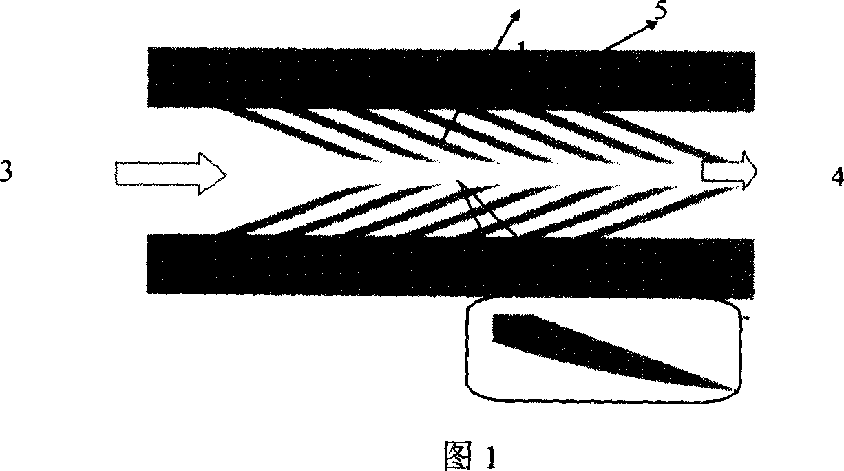
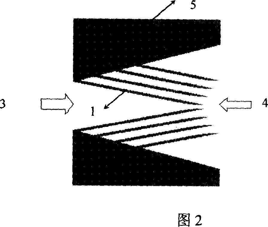
[0021] Embodiment 1: The valve body includes a micro-channel 5 and a parallel arrangement of micro-movable scale structures 1 connected to its side wall. The micro-channel can be a columnar structure, or a diffusion tube structure with a certain cone angle. As shown in Figure 2, the micro-scales 1 should be arranged along the direction of diffusion. Here, the micro-movable scales 1 play the role of valve plates. The opening and closing of the scales 1 cater to the inertial flow inside the fluid. When the fluid flows in the opposite direction, the resistance is small and the flow is smooth; on the contrary, when the fluid flows against the direction of the scales 1, the scales 1 are opened, and the distance of the flow channel is narrowed. At the same time, the reverse disturbance is increased, so that the reverse The flow rate decreases, and the flow rate in the forward direction is greater than the flow rate in the reverse direction, which can play the role of a one-way valve....

Embodiment 2

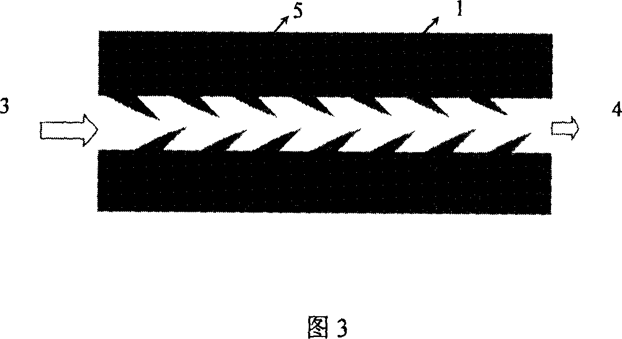
[0022] Embodiment 2: The valve body includes a micro-channel 5 and a micro-fixed scale structure 1 connected to its vertical side wall. The fixed scale can be a structure similar to a shark fin, or a fixed sheet structure, and the micro-scale structures are parallel to each other. Arrangement, wherein each group of micro scales on the side wall of the flow channel are interspersed with each other or arranged symmetrically. As shown in Figure 3; the micro-channel 5 can be columnar; the two side walls of the micro-channel 5 can also form a certain angle to form a diffusion pipe flow channel 5 (the flow in the diffusion direction is large, and the scales should be arranged along the direction of diffusion) The layout is shown in Figure 4. The main function of the fixed scales is to minimize the disturbance along the flow direction and increase the disturbance against the flow direction, thus changing the flow resistance characteristics of the micro-channel and increasing the effic...


PUM


Abstract

This invention provides one micro valve formed by micro fin in micro flow control field, which comprises micro flow channel and micro fin array structure connected distributed parallel at one angle to flow channel side wall along fin distribution direction flow and positive flow. Due to positive fin resistance force the inverse fin slice generates large resistance to generate flow difference to realize single valve function.

Description

technical field [0001] The invention belongs to the field of microfluidic control transportation, in particular to a miniature passive valve that can be directly integrated in a flow channel. Background technique [0002] The microvalve is a key component in the microfluidic chip. It is mainly used to control the flow direction of the fluid and quantitatively control the fluid flow. It plays an important role in the microfluidic analysis chip. Scientific and technological workers have been committed to the research and development of micro valves for many years. At present, the visible micro valves are mainly divided into active valves and passive valves: active valves refer to the use of the actuation force generated by the actuator to realize the closing or switching of the valve. Its main characteristics are strong actuation force and good sealing performance of the valve, which can be used for both one-way valve and switching valve, but the ensuing limitations are also v...

Claims


Application Information

Patent Timeline
IPC IPC(8): F16K17/20
Inventor 李修函于晓梅张大成李婷王颖王玮罗葵王阳元
Owner PEKING UNIV
Why Eureka
Try Eureka