Transflective liquid crystal display with patterned optical layer
A liquid crystal display, transflective technology, used in the manufacture of such displays, in the field of patterned optical layers, can solve problems such as not, reduce contrast, image sharpness, blurring, etc., achieve easy manufacturing, avoid parallax problems, and optimize optical properties. Effect
- Summary
- Abstract
- Description
- Claims
- Application Information
AI Technical Summary
Problems solved by technology
Method used
Image
Examples
example 1
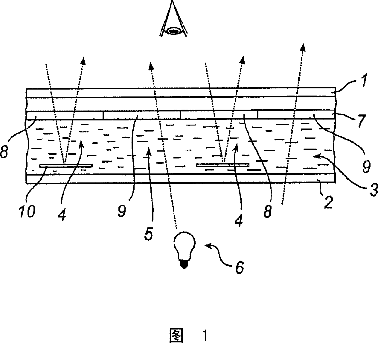
[0096] The substrate is provided with an alignment layer (rubbed polyimide or photo-alignment layer). A mixture of active LC materials including some (active) isomerizable chiral compounds is spin-coated on top of the alignment layer, which provides a layer of cholesteric ordered material with a cholesteric pitch less than or equal to 300 nm. The mixture may further include a reactive achiral LC, a non-isomerizable chiral compound and a photoinitiator. The layer can be irradiated in a desired pattern so that in the irradiated regions (where the layer has become nematic) the isomerizable chiral compound is switched and the cholesteric pitch is increased to infinity. This can be achieved if the helical twisting power (HTP) of the isomerizable chiral compound is zero at the time of the switch, or if the product of the HTP times the concentration of the isomerizable chiral compound is divided by the HTP and the HTP present in the mixture after the switch The products of the conce...
example 2
[0099] In this second approach, active chiral LC compounds or mixtures of (chiral) active LC materials are used which exhibit a chiral nematic (cholesteric) phase as well as a smectic A phase. The material or mixture is spin-coated on a substrate provided with an alignment layer. At low temperatures, the material is in the smectic A phase and in this way forms a uniaxial retardation layer after spin coating. Irradiating the layer according to the desired pattern will produce photopolymerization in the irradiated areas. Subsequently, the temperature is raised above the transition temperature from the smectic A phase to the cholesteric phase. In non-aggregated regions, the order will change from stratified to cholesteric, while the hierarchical order will remain in aggregated regions. Flood exposure at elevated temperature will freeze the cholesteric order by photopolymerization and produce a patterned optical layer.
example 3
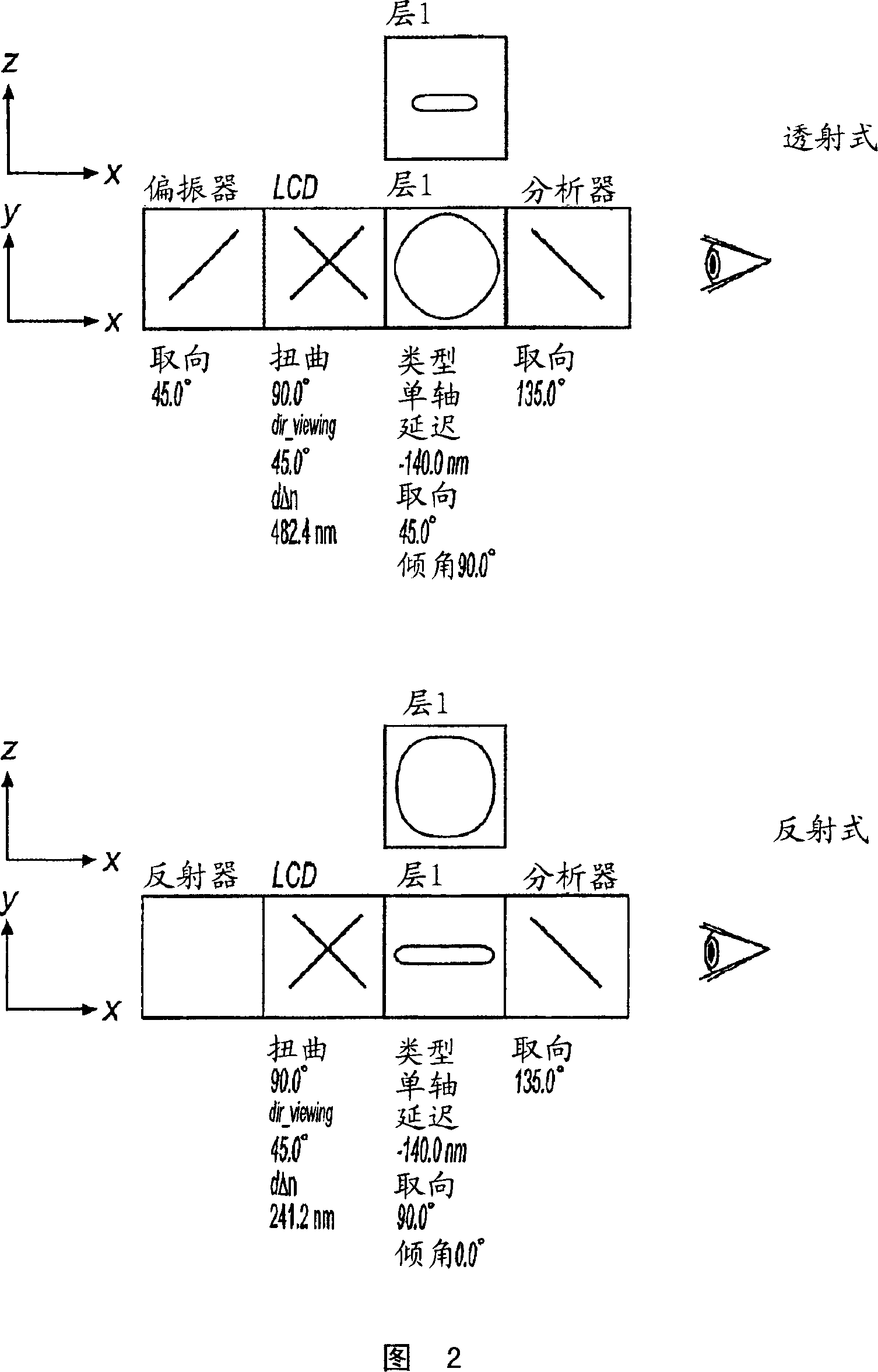
[0101] Biregions are prepared for example according to the methods described by Imura et al., J Photopolym Sci Technol 8, p. 257 (1995) and Schadt et al., Nature 381, p. 212 (1996) or other methods known to those skilled in the art A photoaligned alignment film where the director orientation is determined by the polarization of the UV light used during the two-step UV exposure. Liquid crystal mixture RMM34 (available from Merck) was spin-coated on top of a dual domain light alignment film, eg LPP 265 CP layer. This achieves planar alignment of the active LC monomers. Exposure through a UV mask under a nitrogen atmosphere partially cross-linked the optical layer to freeze into the desired planar state (tilt angle of 0°) required for λ / 4 retardation in the reflective portion of the pixel. The optical layer is then annealed at elevated temperature for about 10 minutes. During the annealing step, the volatile surfactants in the liquid crystal mixture are evaporated, so that a sp...
PUM
 Abstract
Description
Claims
Application Information
 - Generate Ideas
- Intellectual Property
- Life Sciences
- Materials
- Tech Scout
- Unparalleled Data Quality
- Higher Quality Content
- 60% Fewer Hallucinations
Browse by: Latest US Patents, China's latest patents, Technical Efficacy Thesaurus, Application Domain, Technology Topic, Popular Technical Reports.
© 2025 PatSnap. All rights reserved.Legal|Privacy policy|Modern Slavery Act Transparency Statement|Sitemap|About US| Contact US: help@patsnap.com


