Driving system for LCD

A technology of liquid crystal display and driving system, which is applied in the direction of static indicators, instruments, etc.

Active Publication Date: 2007-02-28
INNOLUX CORP
View PDF0 Cites 6 Cited by
  • Summary
  • Abstract
  • Description
  • Claims
  • Application Information

AI Technical Summary

Problems solved by technology

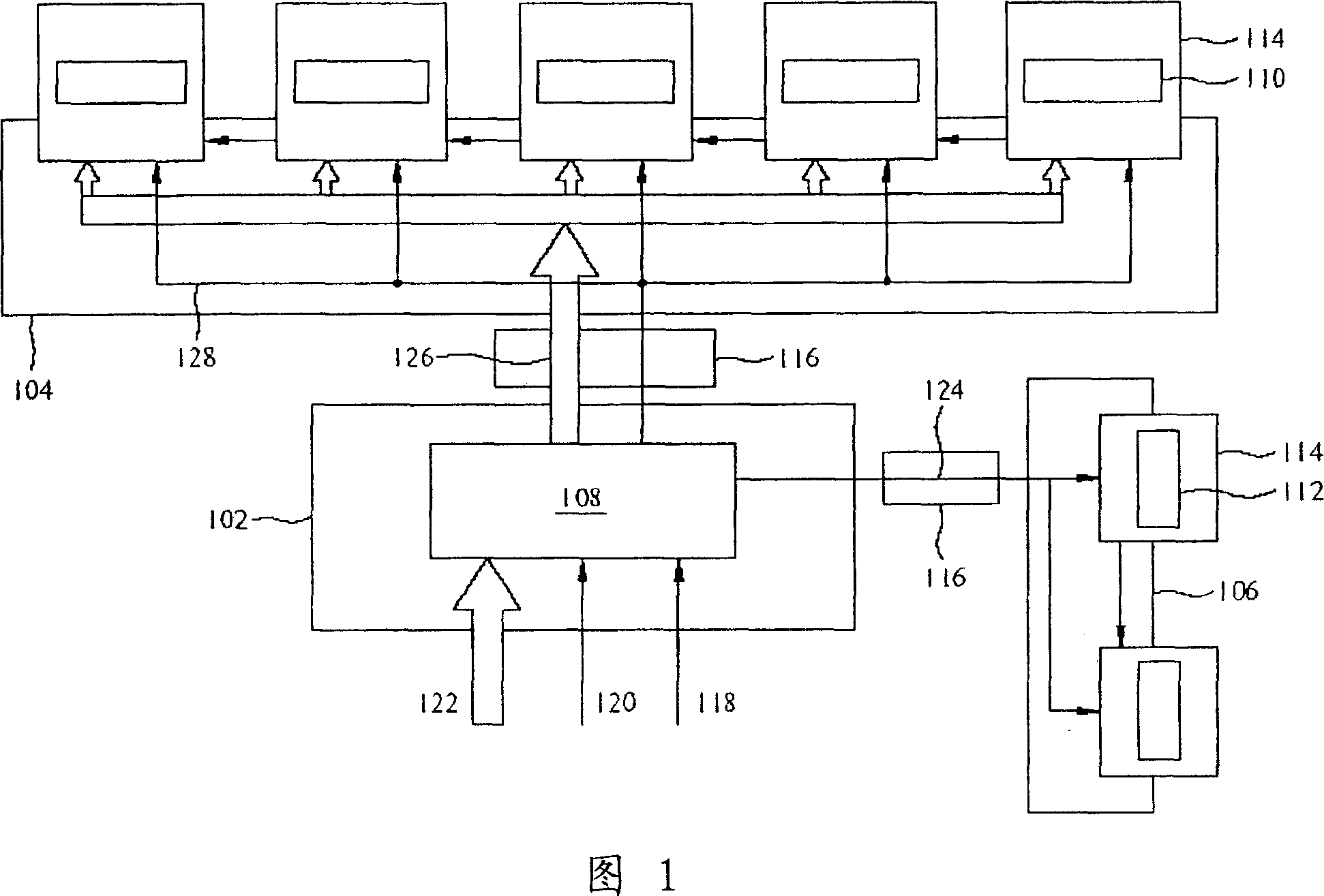
Wherein, the data 126 is substantially the same as the pixel data 122, however, the input of the pixel data 122 and the output of the data 126 occupy most of the pins of the timing control circuit 108, which becomes a major obstacle to cost reduction.

Method used


Image

  • Driving system for LCD
  • Driving system for LCD
  • Driving system for LCD

Examples


Embodiment Construction

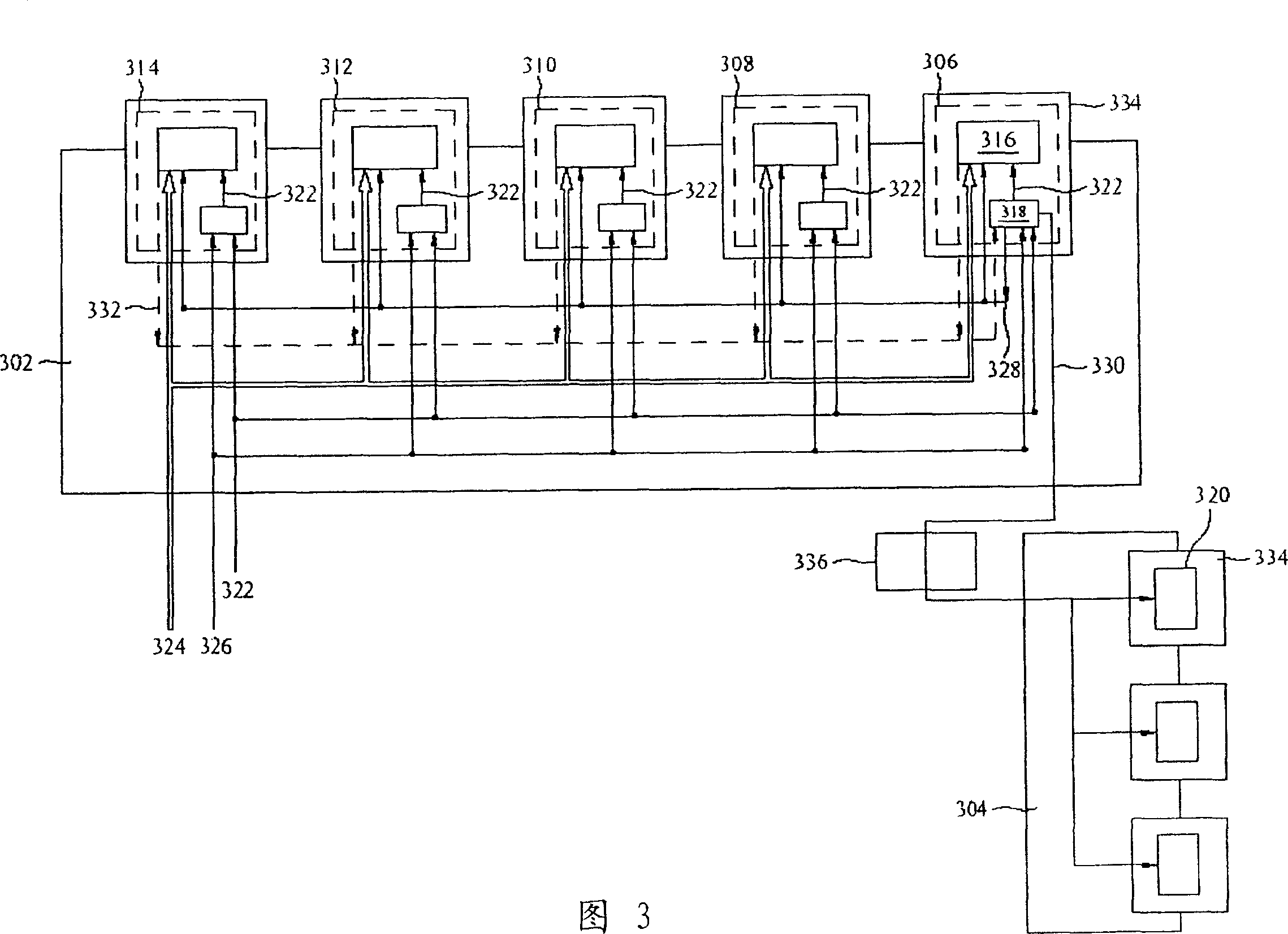
[0055] In order to make the description of the present invention more detailed and complete, reference may be made to the following description in conjunction with the diagrams of FIG. 2 , FIG. 3 and FIG. 4 .

[0056] Please refer to FIG. 2 , which shows a schematic diagram of a driving system of a liquid crystal display according to an embodiment of the present invention. The driving system of this embodiment at least includes a source driving circuit 210 , a gate driving circuit 212 and a timing control circuit 208 . The timing control circuit 208 is located on the control board 202 , and compared with the conventional timing control circuit, the timing control circuit 208 has fewer pins and a smaller volume. The source drive circuit 210 is connected to the X board 204, and the gate drive circuit 212 is connected to the Y board 206, wherein the X board 204 and the Y board 206 are used for processing electrical signals, and the source drive circuit 210 and the gate drive circ...


PUM


Abstract

The invention relates to a driving system of liquid crystal display, wherein it comprises a pixel data line, a sequential control circuit, a source driving circuit and a grid driving circuit; said pixel data line directly supplies the pixel data of source driving circuit; the sequential control circuit receives one time clock and one synchronous signal, to output one source control signal and one grid control signal; the source driving circuit receives said clock signal, source control signal and the pixel signal to output video signal; the grid driving circuit receives the grid control signal to output switch signal.

Description

technical field [0001] The present invention relates to a driving system, and in particular to a driving system applied in a liquid crystal display. Background technique [0002] In recent years, many flat panel display (Flat Panel Display) technologies have been developed one after another. Among them, liquid crystal display (LCD) has the advantages of high image quality, small size, light weight, low voltage drive, low power consumption and wide application range. Therefore, it is widely used in consumer electronics or computer products such as medium and small portable TVs, mobile phones, video recorders, notebook computers, desktop monitors, and projection TVs, and has gradually replaced cathode ray tubes. (Cathode Ray Tube; CRT) has become the mainstream of future displays, especially thin film transistor (Thin Film Transistor; TFT) liquid crystal displays, because of their high display quality and low power consumption, almost occupy most of the market. [0003] In th...

Claims


Application Information

Patent Timeline
Patent Type & Authority Applications(China)
IPC IPC(8): G09G3/36G09G3/20G02F1/133
Inventor 林文聪
Owner INNOLUX CORP
Why Eureka
Try Eureka