Method of full light control laser synchronization
A technology of lasers and lasers, applied in lasers, laser components, optics, etc., can solve problems such as unrealizable, unrealizable long-distance light control, etc., and achieve the effect of small time jitter
- Summary
- Abstract
- Description
- Claims
- Application Information
AI Technical Summary
Problems solved by technology
Method used
Image
Examples
Embodiment 1
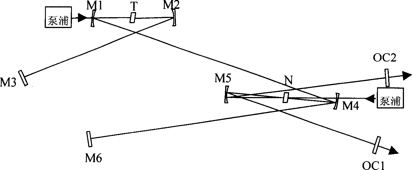
[0028] Embodiment 1: as Figure 4 As shown, this embodiment is a form of expression constituting the above-mentioned structural units. Insert a confocal cavity composed of M4 and M5 into the laser composed of cavity mirrors labeled M1, M2, M3 and OC, place the Kerr medium N at the focus of the confocal cavity, and T is the gain of the laser As the medium, titanium-doped sapphire (Ti:S) is selected in this embodiment. Among them, M1, M2, M4, and M5 are concave mirrors, M3 is a plane mirror, and OC is an output coupling mirror. The cavity mirror is coated with different dielectric coatings for different wavelength bands. M6 and M7 are concave reflectors with the same curvature as M4 and M5, and their function is to focus the laser output from laser 1 onto the Kerr medium. N is the Kerr medium. In this embodiment, titanium-doped sapphire is used and placed in M6, The common focal point of the confocal cavity formed by M7 and the confocal cavity formed by M4 and M5. When the i...
Embodiment 2
[0029] Embodiment 2: as Figure 5 As shown, this embodiment constitutes another form of expression of the above-mentioned structural unit, and its difference from Embodiment 1 is that it does not directly focus the distant laser light into the Kerr medium, but couples it into a In the passive enhancement cavity composed of M6, M7 and plane mirrors M8, M9 (passive cavity for short), the focus of the passive cavity and another laser composed of M1, M2, M3, M4, M5 and OC are in the Kerr medium The focus on . In this way, the light intensity on the Kerr medium can be greatly increased, and the cross-phase modulation effect can be enhanced, which is more conducive to realizing the synchronization of the two beams. The more complicated part of this embodiment is that to couple the distant laser into the passive cavity, it must be ensured that the passive cavity and the distant laser oscillation cavity have exactly the same free spectral region. Therefore, it is necessary to lock t...
Embodiment 3
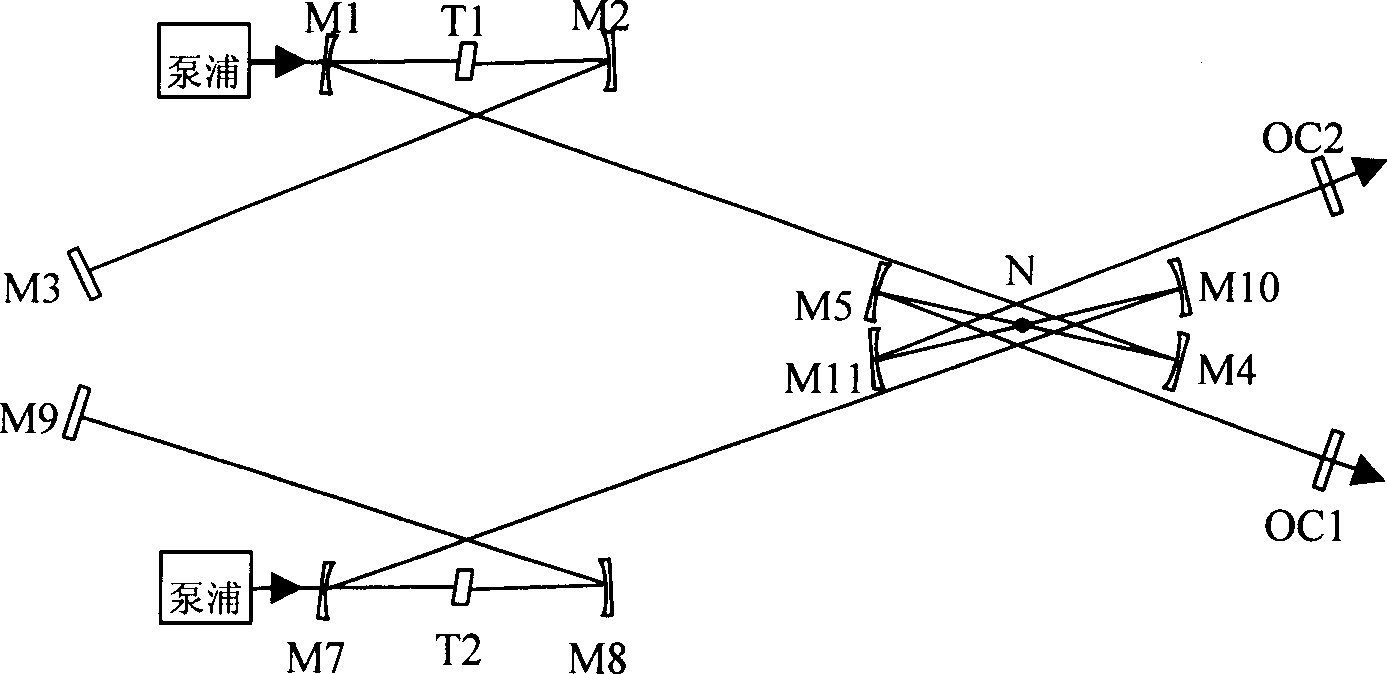
[0030] Embodiment 3: as Figure 6 As shown, the difference between this embodiment and embodiment 1 is that a series-connected all-optical control synchronization system composed of two structures shown in embodiment 2 is adopted, that is, the series connection of two structural units, the principle is the same as that of embodiment 2, and can realize 3-color full optical control synchronization, where M1 and M2 are plane reflectors.
PUM
 Abstract
Description
Claims
Application Information
 - R&D
- Intellectual Property
- Life Sciences
- Materials
- Tech Scout
- Unparalleled Data Quality
- Higher Quality Content
- 60% Fewer Hallucinations
Browse by: Latest US Patents, China's latest patents, Technical Efficacy Thesaurus, Application Domain, Technology Topic, Popular Technical Reports.
© 2025 PatSnap. All rights reserved.Legal|Privacy policy|Modern Slavery Act Transparency Statement|Sitemap|About US| Contact US: help@patsnap.com


