
Welding structure and welding method for aluminum accumulator and heat exchanger

A technology of welded structure and aluminum accumulator, applied in heat exchange equipment, welding equipment, evaporator/condenser, etc., can solve the problems of poor welding, supply, difficult positioning of stainless steel casing 8, etc.

Active Publication Date: 2007-02-07
PANASONIC CORP
View PDF1 Cites 4 Cited by
  • Summary
  • Abstract
  • Description
  • Claims
  • Application Information

AI Technical Summary

Problems solved by technology

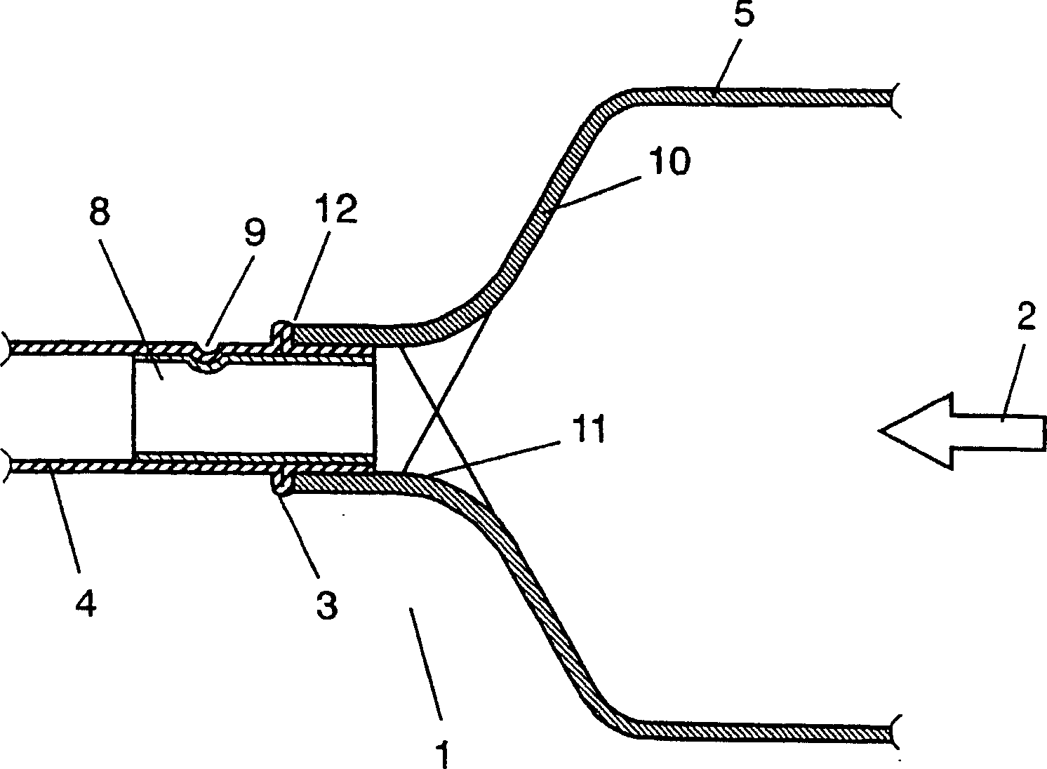
[0006] However, in the above-mentioned conventional structure, since the step 13 provided in the aluminum reservoir 5 makes the wall thickness of the step portion thinner, the amount of aluminum necessary for welding is reduced, so it is necessary to use an aluminum material such as an aluminum filler wire. supply
In this case, if the welding skills are poor, it will not be possible to supply the aluminum material properly, resulting in poor welding
In addition, since the stainless steel sleeve 8 is difficult to position and has poor adhesion to the aluminum conduit 4, there may be poor welding due to slipping or falling during welding.
In addition, when a conventional structure is adopted on the outlet side of the aluminum accumulator, that is, on the downstream side of the refrigerant liquid flow, the stainless steel sleeve 8 protrudes into the aluminum accumulator 5 structurally, thereby hindering the flow. Refrigerator oil flows through the inner wall 11 of the aluminum accumulator to the compressor, resulting in compressor damage and other problems that reduce the reliability of the compressor.

Method used


Image

  • Welding structure and welding method for aluminum accumulator and heat exchanger
  • Welding structure and welding method for aluminum accumulator and heat exchanger
  • Welding structure and welding method for aluminum accumulator and heat exchanger

Examples


Embodiment approach 1

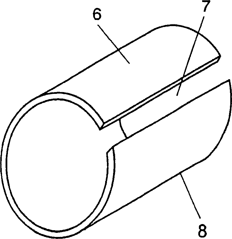
[0037] figure 1 It is a sectional view of the welded structure of the aluminum accumulator according to Embodiment 1 of the present invention, figure 2 It is the perspective view of the stainless steel casing of the same embodiment. figure 1 , figure 2 Among them, the welded structure 1 of the aluminum accumulator is composed of an aluminum conduit 4, an aluminum accumulator 5, and a stainless steel sleeve 8, wherein the aluminum conduit 4 is used in the outlet of an accumulator used in a freezing system such as a refrigerator, It is a heat transfer tube in which the refrigerant 2 flows, and has a weld bead processing part 3; the aluminum liquid receiver 5 has the following functions, that is, the liquid refrigerant is stored, and the liquid refrigerant is not directly sent to the compressor (not diagram) flows, but is utilizing a heat exchanger (using Figure 5 After the heat load of explaining later) it is vaporized, send into compressor; The stainless steel sleeve 8...

Embodiment approach 2

[0047] image 3 It is a cross-sectional view of the welded structure of the aluminum accumulator according to Embodiment 2 of the present invention, Figure 4 It is the perspective view of the stainless steel casing of the same embodiment. image 3 , Figure 4 Among them, the welded structure 1 of the aluminum accumulator is composed of an aluminum conduit 4, an aluminum accumulator 5, and a stainless steel sleeve 8, wherein the aluminum conduit 4 is used in the outlet of an accumulator used in a freezing system such as a refrigerator, It is a heat transfer tube in which the refrigerant 2 flows, and has a weld bead processing part 3; the aluminum liquid receiver 5 has the following functions, that is, the liquid refrigerant is stored, and the liquid refrigerant is not directly sent to the compressor (not diagram) flows, but is utilizing a heat exchanger (using Figure 5 After the heat load of explaining later) it is vaporized, send into compressor; The stainless steel slee...


PUM


Abstract

A welding structure and a welding method for an aluminum accumulator capable of reducing defective welding and smoothly flowing a refrigerating machine oil and a heat exchanger. The welding structure for the aluminum accumulator comprises an aluminum pipe having a beading processed part, the aluminum accumulator, and a stainless steel sleeve. The stainless steel sleeve is inserted into the end part of the aluminum pipe so that the end face of the stainless steel sleeve matches the end face of the aluminum pipe. The aluminum pipe is inserted into the aluminum accumulator up to the beading processed part, and the aluminum pipe and the aluminumaccumulator are welded to each other at a joint part where the aluminum pipe, the aluminum accumulator, and the stainless steel sleeve are overlapped with each other.

Description

technical field [0001] The present invention relates to a welding structure and a welding method of an aluminum accumulator, and a heat exchanger provided with the welded structure of the aluminum accumulator. Background technique [0002] In general, in heat exchangers used in household refrigerators and the like, a welded structure of an aluminum accumulator and an aluminum conduit is known as a welded structure of the accumulator that is inserted between the aluminum accumulator and the aluminum conduit. The inner circumference of the connection part has a stainless steel sleeve, and the outer circumference of the connection part is welded. However, in recent years, since further cost reductions have been achieved in home appliances such as refrigerators, and flammable refrigerants have been used as the medium used, cost reductions are also required in heat exchangers, which are internal functional components. , and require improved welding reliability. However, welding...

Claims


Application Information

Patent Timeline
IPC IPC(8): B23K9/00B23K9/23F25B39/02F25B43/00B23K31/02F25B39/00F25B41/00F28F9/26
CPCB23K31/02F25B39/00F25B41/003F28F9/26F25B43/006B23K2201/14B23K2101/14F25B41/40
Inventor 伊藤和彦
Owner PANASONIC CORP
Learn More