Rope for elevator and elevator
A rope and elevator technology, applied in textile cables, transportation and packaging, textiles and papermaking, etc., can solve the problem of insufficient assembly density of steel wire rods
- Summary
- Abstract
- Description
- Claims
- Application Information
AI Technical Summary
Problems solved by technology
Method used
Image
Examples
Embodiment approach 1
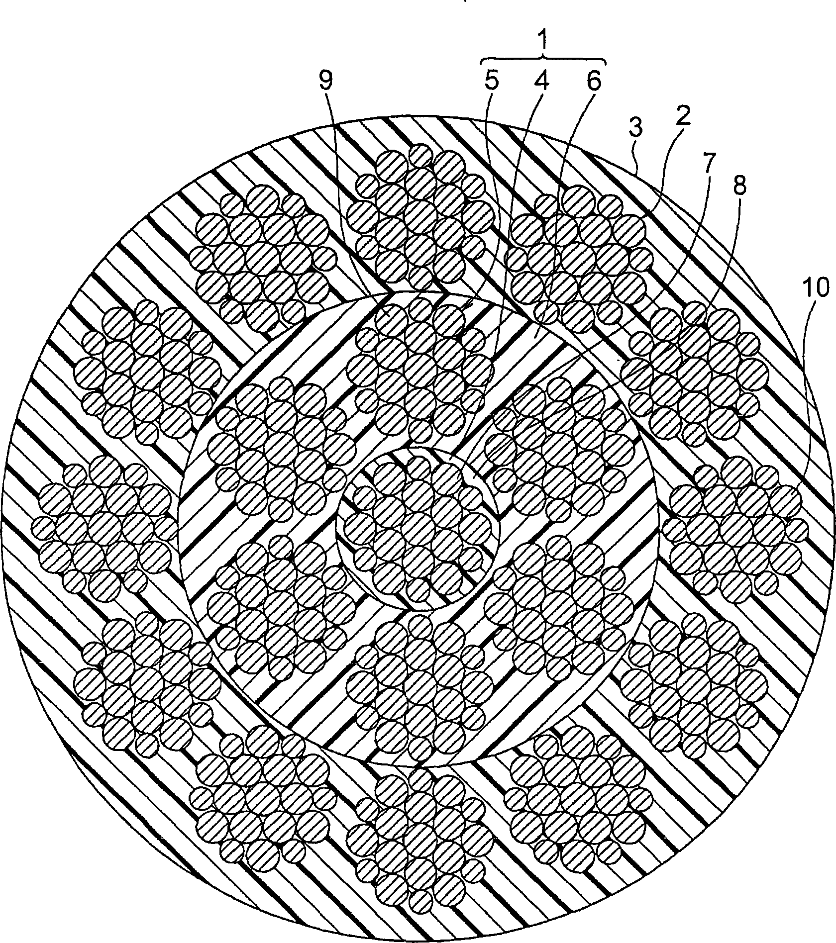
[0018] figure 1 is a cross-sectional view of an elevator rope according to Embodiment 1 of the present invention, figure 2 is split by layer figure 1 A side view of an elevator represented with ropes.
[0019] In the figure, the elevator rope includes: a core rope 1 ; an outer layer strand assembly 2 provided on the outer periphery of the core rope 1 ; and a resin outer layer covering body 3 covering the outer layer strand assembly 2 . The core rope 1 includes: a core rope 4 ; a core rope sub-rope assembly 5 provided on the outer periphery of the core rope 4 ; and a resin core rope covering body 6 covering the core rope sub-rope assembly 5 .
[0020] The core rope 4 has: a core rope main body 7 formed by twisting a plurality of steel wire rods; and a resin core rope covering body 8 covering the core rope main body 7 .
[0021] The core rope sub-rope assembly 5 is composed of a plurality of (here, six) core rope sub-ropes 9 . In this example, each core rope sub-rope 9 is o...
Embodiment approach 2
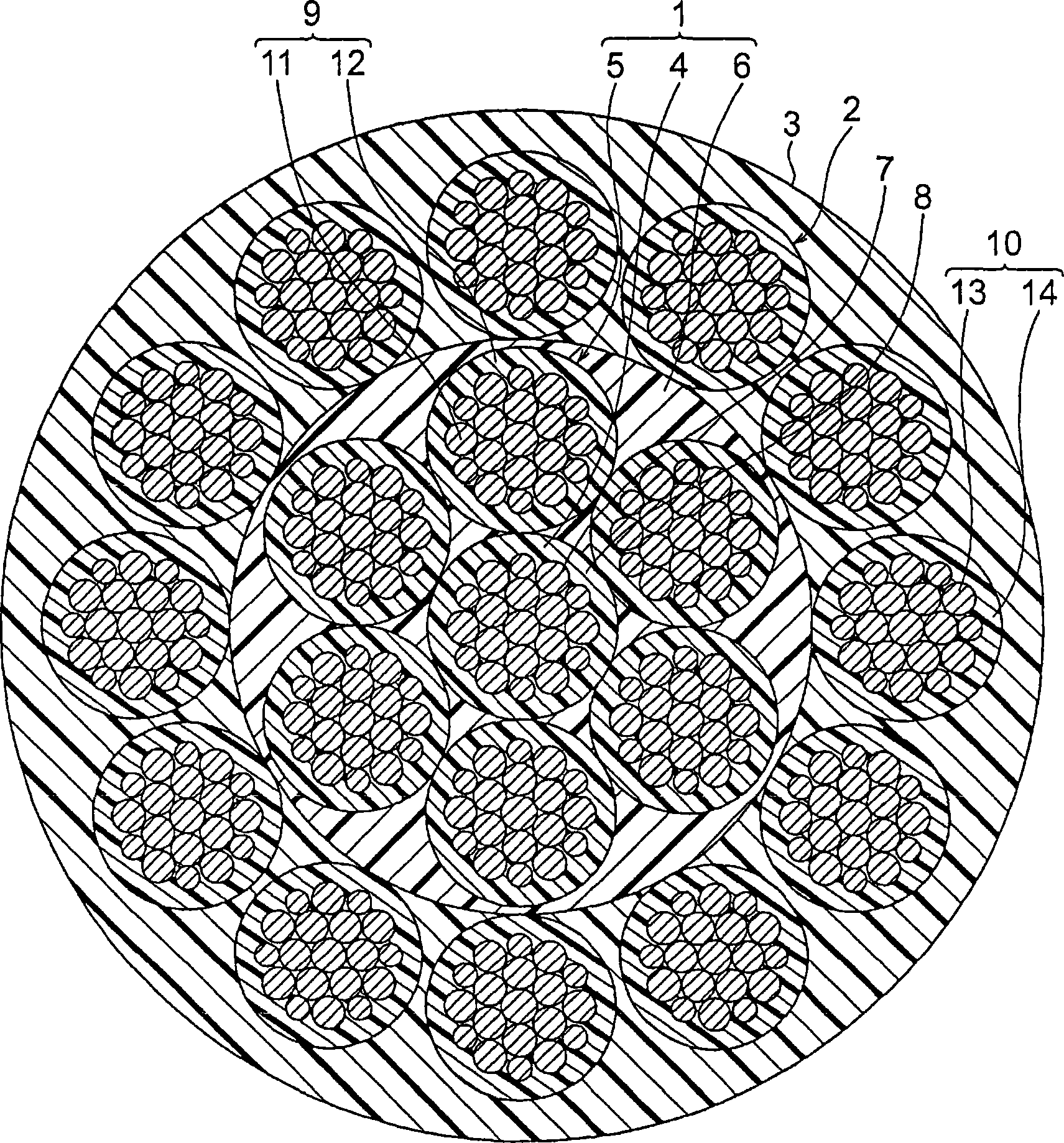
[0039] under, image 3 It is a cross-sectional view of an elevator rope according to Embodiment 2 of the present invention. In the figure, the core rope sub-rope 9 has: a core rope sub-rope main body 11 formed by twisting a plurality of steel wire rods, and a resin core rope sub-rope covering body 12 covering the core rope sub-rope main body 11 . In addition, the outer layer strand 10 has an outer layer strand main body 13 formed by twisting a plurality of steel wire rods, and a resin outer layer strand covering body 14 covering the outer layer strand main body 13 . The core rope sub-rope covering body 12 and the outer layer sub-rope covering body 14 are made of the same material as the core rope covering body 8 and the core rope covering body 6 , for example, polyethylene resin. Other structures are the same as those in Embodiment 1.
[0040] In such elevator ropes, since the covering bodies 8, 12, 14 are provided on the outer peripheries of all the strands 4, 9, 10, durin...
Embodiment approach 3
[0042] under, Figure 4 A cross-sectional view showing an elevator rope according to Embodiment 3 of the present invention. In the figure, the outer layer sub-rope 10 is only composed of the main body of the outer layer sub-rope, and the outer layer sub-rope main body is formed by twisting a plurality of steel wires. In the outer layer strand main body, by compressing the outer layer strand main body from the outer periphery, the cross section of the steel wire rod is deformed. Other structures are the same as those in Embodiment 2.
[0043] In such an elevator rope, when the distance between the adjacent outer layer strands 10 is small, even if the outer layer strands 10 are in contact with each other, the contact pressure can be reduced. Furthermore, the packing density of the steel wires of the outer layer strands 10 can be increased.
[0044] In this way, the cross-sectional structures of the sub-strings 4, 9, 10 of each layer can also be made different from each other....
PUM
| Property | Measurement | Unit |
|---|---|---|
| diameter | aaaaa | aaaaa |
| friction coefficient | aaaaa | aaaaa |
Abstract
Description
Claims
Application Information
 - R&D
- Intellectual Property
- Life Sciences
- Materials
- Tech Scout
- Unparalleled Data Quality
- Higher Quality Content
- 60% Fewer Hallucinations
Browse by: Latest US Patents, China's latest patents, Technical Efficacy Thesaurus, Application Domain, Technology Topic, Popular Technical Reports.
© 2025 PatSnap. All rights reserved.Legal|Privacy policy|Modern Slavery Act Transparency Statement|Sitemap|About US| Contact US: help@patsnap.com


