
Method for no-damage switching in radio cut-in technology

A wireless access technology and downlink data technology, which is applied in the field of lossless handover and can solve the problems of time extension, large storage space, increased system signaling and data transmission overhead, etc.

Active Publication Date: 2012-02-29
HUAWEI TECH CO LTD
View PDF0 Cites 0 Cited by
  • Summary
  • Abstract
  • Description
  • Claims
  • Application Information

AI Technical Summary

Problems solved by technology

[0030] The purpose of the present invention is to provide a method for lossless handover in wireless access technology. Through the present invention, the lossless transmission of business data can be guaranteed, and the comparison of data packet loss rate when ASN-GW handover occurs in the prior art is solved. High problem, and after adopting the retransmission mechanism, the problem of longer delay and the increase of system signaling and data transmission overhead; solves the problem that the ASN-GW must set a queue or buffer in the ASN-GW in the prior art and requires the ASN-GW There is a problem with a large storage space, and the lossless migration process of the present invention is completely carried out in the ASN, and the establishment of a new R3 does not require additional functions of the CSN side equipment, thus reducing the requirements and dependence on the CSN

Method used

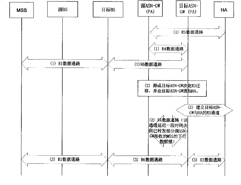

Image

  • Method for no-damage switching in radio cut-in technology
  • Method for no-damage switching in radio cut-in technology
  • Method for no-damage switching in radio cut-in technology

Examples


no. 1 example

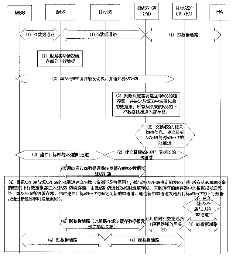
[0109] The first embodiment provided by the present invention, such as figure 2 shown, including:

[0110] Step 101. Establish a buffer in the source ASN-GW.

[0111] This process specifically includes two situations.

[0112] One is: according to the QoS requirement of the service and / or the level of the user, statically establish a buffer in the source ASN-GW.

[0113] The second is: when an ASN-GW switch occurs, a buffer is dynamically established in the source ASN-GW according to the QoS requirement of the service and / or the class of the user. Specifically, this process includes:

[0114] Step 1: When the source BS negotiates with the MSS to trigger the handover, the source ASN-GW is notified by sending a handover message;

[0115] Step 2. When the source ASN-GW receives the handover message, dynamically establish a buffer in the source ASN-GW according to the QoS requirement of the service and / or user level.

[0116] When the MSS moves from the source BS to the rang...

no. 3 example

[0154] The third embodiment provided by the present invention includes:

[0155] Step 301, establishing a buffer in the source BS.

[0156] This process specifically includes two situations.

[0157] One is: according to the QoS requirement of the service and / or the class of the user, a buffer is statically established in the source BS.

[0158] The second is: when handover occurs, a buffer is dynamically established in the source BS according to the QoS requirement of the service and / or the class of the user. Specifically, this process includes:

[0159] Step 1, the source BS negotiates with the MSS to trigger handover;

[0160] Step 2: After the negotiation between the source BS and the MSS is completed, a buffer is dynamically established in the source BS according to the QoS requirement of the service and / or the class of the user.

[0161] When the MSS moves from the source BS to the range covered by the target BS, or in the range covered by the source BS and the targe...


PUM


Abstract

This invention relates to a method for carrying out non-loss switch in a radio access technology including: transmitting the MSS data sent to a source NE to a corresponding target NE via the data channel between the source NE and a target NE when switching, and conveying the MSS data messages to said target NE, which transfers the received data messages to the corresponding MSS to ensure the non-loss transmission of service data.

Description

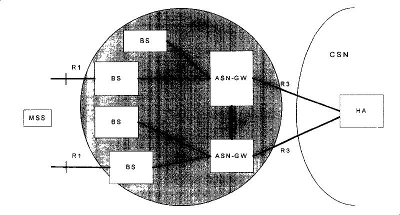
technical field [0001] The invention relates to the communication field, in particular to a method for lossless switching in wireless access technology. Background technique [0002] With the vigorous development of Internet services and the wide application of wireless networks, the number of mobile users has increased rapidly, and the demands of users have also increased rapidly. This undoubtedly requires wireless technologies such as GPRS (General Packet Radio Service), Wireless technologies such as 3G, WiMAX and B3G (Beyond 3G; post-3G) can support multiple services with large capacity, large data volume and different service quality requirements. [0003] As a bridge between wireless users and existing wired networks or other service networks, wireless access technology mainly completes the function of forwarding or routing packet services between the network and mobile users. [0004] Below as figure 1 The shown WiMAX network architecture system is taken as an exampl...

Claims


Application Information

Patent Timeline
Patent Type & Authority Patents(China)
IPC IPC(8): H04L12/56H04W36/02H04W28/04H04W36/18
Inventor 吴建军
Owner HUAWEI TECH CO LTD
Learn More