Multi-mode interference beam splitter and apparatus and method for preparing the same

A multi-mode interference and beam splitter technology, applied in the direction of optical waveguide and light guide, can solve the problems of increased optical transmission loss, difficulty in controlling the preparation process, and large wafer area.

Inactive Publication Date: 2006-12-27
PEKING UNIV
View PDF0 Cites 2 Cited by
  • Summary
  • Abstract
  • Description
  • Claims
  • Application Information

AI Technical Summary

Problems solved by technology

However, the angle between these two components is very small, so it is difficult to control its manufacturing process
Moreover, if the multi-access transmission function is to be realized, a large number of branch waveguides and optical switch units are required to form a large-scale matrix connected by a dendritic network, which not only lengthens the cumulative optical path connected to the optical waveguide, but also complicates the network distribution and reduces the chip area. It is very large, and the loss of optical transmission will also increase

Method used


Image

  • Multi-mode interference beam splitter and apparatus and method for preparing the same
  • Multi-mode interference beam splitter and apparatus and method for preparing the same
  • Multi-mode interference beam splitter and apparatus and method for preparing the same

Examples


Embodiment 1

[0074] Embodiment 1: Single MMI waveguide structure beam splitter and its preparation device and method

[0075] Such as Figure 5 Shown is a schematic diagram of a device for preparing a multimode interference beam splitter (MMI), including: ultrashort pulse laser 1, energy and pulse width tuning measurement device 3, shutter 4, beam shaping and filter 5, focusing objective lens 6, Three-dimensional numerical control translation platform 8, CCD detector 9, signal transmission line 10 and computer 11, the connection relationship between each component is as follows Figure 5 As shown, among them, the energy and pulse width tuning measurement device 3, the shutter 4, the three-dimensional numerical control translation stage 8 and the CCD detector 9 are all connected to the computer through the signal transmission line. Among them, the ultrashort pulse laser 1 adopts a titanium sapphire femtosecond laser, and its output laser beam 2 has a wavelength of about 800 nm (nanometer) ...

Embodiment 2

[0079] Example 2: An array beam splitter composed of double MMI beam splitters and its preparation device and method

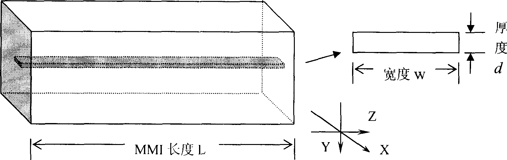
[0080] The device for preparing the array beam splitter composed of double MMI beam splitters is the same as the device in Embodiment 1, and the steps are basically the same. The specific process is as follows: the laser beam 2 output by the ultrashort pulse laser 1 is subjected to beam shaping and filter 5 filtering The spatial fundamental mode is obtained, after the energy attenuator and the energy meter (not shown in the figure) are adjusted to obtain the appropriate energy, the shutter 4 is used to focus on the sample 7 on the three-dimensional numerically controlled translation stage 8 with the focusing objective lens 6, and the The samples are made of fused silica. The single pulse energy used was about 2.0 μJ, and the filaments produced due to the refractive index change in the sample 7 caused by the laser beam were about 200 μm. When the vertical self...


PUM


Abstract

The invention relates to a multi-mode interface (MMI) beam splitter, relative preparing device and method, wherein said MMI beam splitter comprises a transparent electric medium sample and internal formed three-dimension multi-mode interface optical waveguide; said preparing device comprises a laser used to generate laser beam; an adjuster for adjusting the laser energy and pulse width; a shutter for controlling the laser exposure; a filter for rectifying and filtering the laser beam; a focus device for focusing the laser beam; a working platform for loading and moving sample; a synchronous detector for detecting the laser beam input state; and a controller for controlling the shutter and movable platform via feedback information of detector. And said preparing method comprises: it uses focus object lens with low numerical aperture, to focus the ultra-short laser into transparent electric medium material to be threaded; and one-time prepares MMI beam splitter; generating laser pulse; rectifying and filtering; focusing; positioning; and writing.

Description

technical field [0001] The invention belongs to the field of optical information processing and precision micro-optoelectronic devices, in particular to a multi-mode interference beam splitter and its preparation method and device. The preparation method is a method for preparing a multimode interference (MMI, Multimode Interference) beam splitter and related photonic devices in a transparent material body by using ultrashort laser pulses. Background technique [0002] Beam splitter is a key component of optical information processing system and optical communication system, and also an important part of integrated optics. Common beam splitters include optical power splitters, TE / TM mode splitters, M-Z optical switches, optical splitters / combiners, etc. Among the traditional beam splitting devices, there are mainly Y branch waveguides and X branch waveguides for 3dB light splitting. However, the angle between these two components is very small, so it is difficult to contro...

Claims


Application Information

Patent Timeline
Patent Type & Authority Applications(China)
IPC IPC(8): G02B6/10
Inventor 李焱郭亨长蒋红兵杨宏龚旗煌
Owner PEKING UNIV
Why Eureka
Try Eureka