


Quick Research
Generate reliable direction feasibility study reports for your R&D in just a few steps.

Technical Q&A
Discover and master advanced knowledge NOW. Basics, ideas, possibilities, all at once.

Find Solutions
As an expert in R&D theories, this can generate solutions to your technical problems instantly.

Evaluate Feasibility
Analyze your overall solution with one click, know your potential R&D risks in advance.

Monitor Landscape
Get weekly tech updates, stay abreast of the latest tech innovations and key insights.
Ballast and projector
A ballast and trigger technology, applied in the field of projectors, can solve problems such as slow rise in electrode temperature, increased insulation tolerance, poor lighting, etc.
- Summary
- Abstract
- Description
- Claims
- Application Information
AI Technical Summary
Problems solved by technology
Method used
Image


Examples
Embodiment approach 1
[0023] figure 1 It is a circuit diagram of the ballast according to Embodiment 1 of the present invention. The ballast is composed of a rectifier circuit 2 for rectifying the AC power source 1, an inverter 3, a trigger transformer 4, a trigger transformer drive circuit 5, and a control unit 6. The output terminal of the trigger transformer 4 is connected to a high-pressure discharge lamp 7 . The rectifier circuit 2 is composed of an inductor L1, a switching element S1, and a diode D. As shown in FIG. The inverter 3 is composed of four switching elements S2-S5 that are fully bridged. The switching elements S2, S5 and S4, S3, through alternate conduction control, convert the DC voltage from the rectifier circuit 2 into an AC voltage, and output it to Trigger Transformer4. The trigger transformer 4 outputs a high voltage to the high pressure discharge lamp 7 as will be described later. The high-pressure discharge lamp 7 is a reflective light source device, and the luminous tu...
Embodiment approach 2
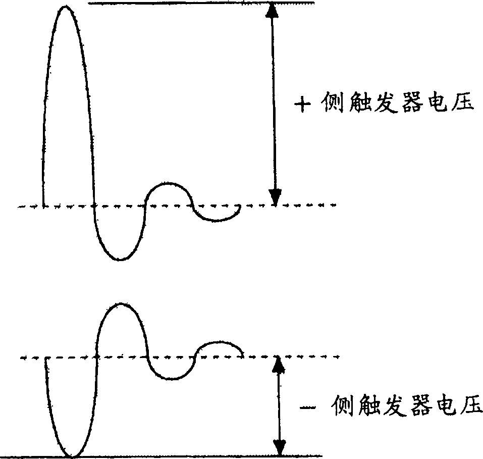
[0029] Figure 4 It is a circuit diagram of the flip-flop transformer 4 according to Embodiment 2 of the present invention. The trigger transformer 4 is composed of two trigger transformers 4a and 4b. When the excitation current is supplied to the respective primary coils T1a and T1b under the control of the trigger transformer drive circuit 5, the secondary coils T2 and T3 can obtain and image 3 The waveforms shown are the same as the output voltage.
Embodiment approach 3
[0031] Figure 5 It is a configuration diagram of an optical system of a projector incorporating the ballasts of Embodiments 1 and 2 described above in an illumination optical system. in addition, Figure 5 The Ballast 10 includes figure 1 The rectifier circuit 2, the inverter 3, the trigger transformer 4, the trigger transformer drive circuit 5, and the control unit 6 make the high-pressure discharge lamp 7 of the illumination optical system 100 light as described above, thereby preventing the In some cases, the lighting failure of the high-pressure discharge lamp may occur.
[0032] The projector has: an illumination optical system 100, dichroic mirrors 210, 212, reflection mirrors 220, 222, 224, an incident side lens 230, a relay lens 232, three field lenses 240, 242, 244, three liquid crystal panels 250, 252 , 254 , polarizers 251 , 253 , 255 , 256 , 257 , and 258 , cross dichroic prism 260 , and projection lens 270 respectively disposed on the output side and incident ...
PUM
 Abstract
Description
Claims
Application Information
 - R&D Engineer
- R&D Manager
- IP Professional
- Industry Leading Data Capabilities
- Powerful AI technology
- Patent DNA Extraction
Browse by: Latest US Patents, China's latest patents, Technical Efficacy Thesaurus, Application Domain, Technology Topic, Popular Technical Reports.
© 2024 PatSnap. All rights reserved.Legal|Privacy policy|Modern Slavery Act Transparency Statement|Sitemap|About US| Contact US: help@patsnap.com