Bulb sockets and lighting fixtures

A technology for light bulbs and sockets, applied in the field of lighting devices, can solve problems such as the increase in the number of components, and achieve the effect of suppressing excessive deformation

Active Publication Date: 2017-05-03
YAZAKI CORP
View PDF6 Cites 0 Cited by
  • Summary
  • Abstract
  • Description
  • Claims
  • Application Information

AI Technical Summary

Problems solved by technology

[0007] However, a conventional light bulb socket such as the one disclosed in Patent Document 1 has a disadvantage that the conventional light bulb socket requires a spacer 120 as a separate part from the socket 100 to guide the light bulb 110 and restrain the holder 102 excessive deformation, which causes an increase in the number of parts

Method used


Image

  • Bulb sockets and lighting fixtures
  • Bulb sockets and lighting fixtures
  • Bulb sockets and lighting fixtures

Examples


Embodiment Construction

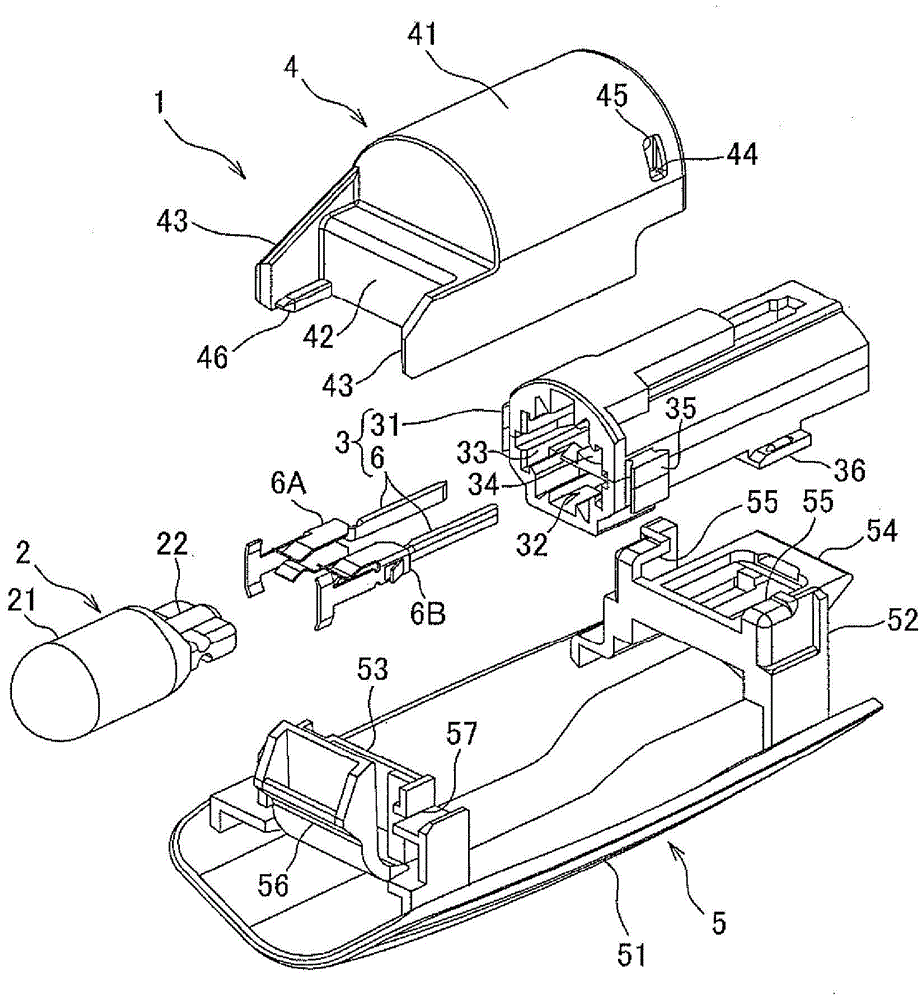
[0061] Below, will refer to figure 1 to 7 illustrate a lighting device according to an embodiment of the present invention. The lighting device 1 according to this embodiment is an interior lighting device to be attached to a ceiling trim, a door trim, and the like on the inner surface of a passenger compartment of a vehicle such as an automobile. Specifically, the lighting device 1 is suitable for use as a door light provided on a door trim. Such as figure 1 As shown, the lighting device 1 includes: a light bulb (ie, an electric light bulb) 2; a light bulb socket 3 arranged to hold the light bulb 2; a protective cover 4 arranged to cover the light bulb 2 and the light bulb socket 3; A lens 5 , the transmitting lens 5 is fixed to the bulb socket 3 and the protective cover 4 and is arranged to transmit light emitted from the bulb 2 .

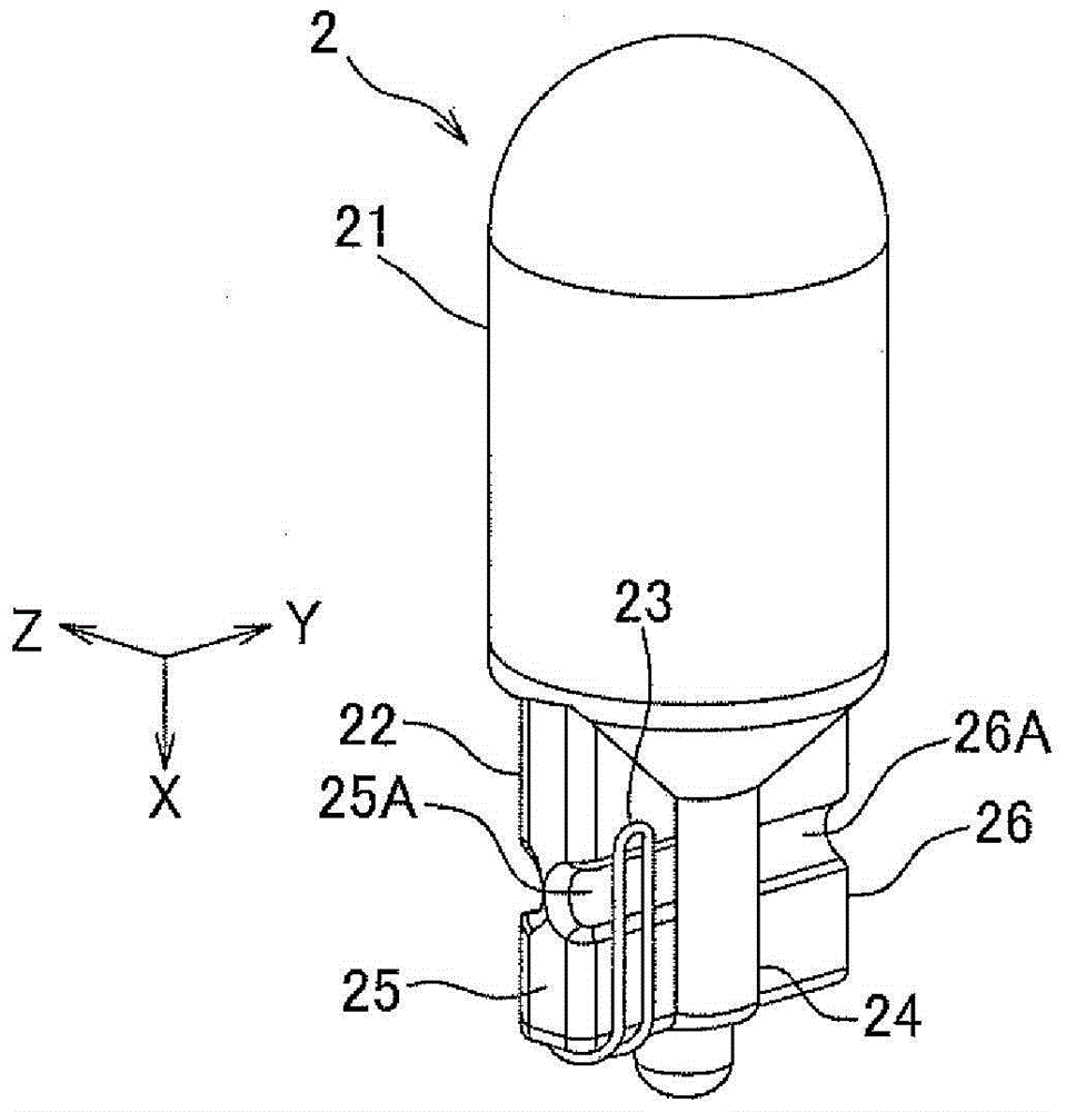
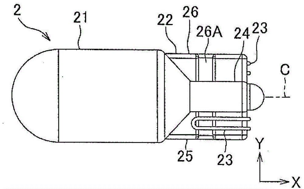
[0062] Such as figure 2 As shown in and 3, the bulb 2 is a wedge-shaped base bulb, and the bulb 2 includes: a light emitting part 21, whi...


PUM


Abstract

A pair of terminal portions of a bus bar (i.e. a terminal clamp) includes spring portions each of which is arranged to exert a pushing force in a direction of sandwiching a base portion of a bulb, and contact portions each provided at a tip portion of the spring portion. A housing (i.e. a socket body) includes regulation portions located on opposite side of the terminal portions and arranged to abut on the terminal portions from opposite side of the base portion to regulate elastic deformation amount of the spring portions to be within a predetermined value.

Description

technical field [0001] The invention relates to a light bulb socket arranged to hold a light bulb and to a lighting device. Background technique [0002] One example of a proposed bulb socket structure used in a vehicle-mounted interior lighting device provided at the roof of a vehicle such as an automobile is provided with a socket body made of resin for mounting such as a wedge-shaped base bulb Such a light bulb; and a pair of power supply terminals (ie, terminal clamps) provided at the socket body, wherein the base (base portion) of the light bulb is inserted into the mounting hole of the socket body, and the pair of power supply terminals Terminal clamping (for example, see Patent Document 1). For the bulb socket structure disclosed in Patent Document 1, as Figure 8 As shown, a pair of power supply terminals 101 is provided with a pair of holders 102 for holding a base 111 of a light bulb 110, so that by inserting the base 111 between the pair of holders 102, the pair ...

Claims


Application Information

Patent Timeline
Patent Type & Authority Patents(China)
IPC IPC(8): H01R33/09
CPCF21V5/04H01R33/09F21V23/06H01R4/48
Inventor 山中秀树村田笃郎小西亮平
Owner YAZAKI CORP
Why Eureka
Try Eureka