
Suction disk loading device and core vibration abatement and core anti-vibration method

A loading device, inhalation technology, applied in the direction of poor vibration/sound insulation/absorption, recording information storage, instruments, etc., can solve problems such as large appearance size, high cost of grease shock pads, and disc loading device not working properly. , to achieve the effect of wide application space and good shock absorption effect

Inactive Publication Date: 2006-11-29
CHANGZHOU SHINCO AUTOMOTIVE ELECTRONICS
View PDF1 Cites 2 Cited by
  • Summary
  • Abstract
  • Description
  • Claims
  • Application Information

AI Technical Summary

Problems solved by technology

[0004] When the disk loading device is placed in the horizontal direction of the movement, the shock-absorbing assembly can make the optical pickup drive part in a suspended state, and elastically support the optical pickup drive part to play a shock-absorbing role; but this shockproof connection assembly The structure is relatively complicated, and the cost of the grease shock absorber is relatively high, and if the movement is placed upright or placed at a large inclination angle relative to the horizontal direction, the driving part of the optical pickup will deviate from the original position due to the effect of gravity. position in the base, so that the shock-absorbing components of the movement will lose the shock-absorbing function, so that the disk loading device cannot work normally; Misalignment of the optical pickup drive unit from its original position in the base also has the potential to prevent the disc loader from functioning properly
[0005] The structure of the disk loading device is relatively complex, and its appearance size is relatively large, and its clamping of the optical disk is realized by moving up and down the drive part of the optical pickup, which will have a certain impact on the service life of the disk loading device

Method used


Image

  • Suction disk loading device and core vibration abatement and core anti-vibration method
  • Suction disk loading device and core vibration abatement and core anti-vibration method
  • Suction disk loading device and core vibration abatement and core anti-vibration method

Examples


Embodiment 1

[0064] (Embodiment 1, the core shock absorber assembly of the suction type disk loading device)

[0065] See Figure 13 to Figure 21 , the core shock absorber assembly of the suction disk loading device has a shock absorber 81, a shock absorber connecting seat 82 and two shock absorbing connectors 83; the shock absorbing connecting seat 82 has a mounting body 822, a connecting body 821 and a positioning body 823; The shock-absorbing connector 83 is a stepped cylinder with a fixed portion 831 and an embedding body 832; the embedding body 832 is composed of an embedding head portion 832-1 and an embedding neck portion 832-2; the diameter of the embedding head portion 832-1 is larger than The diameter of the embedding neck 832-2 is provided with a chamfer 832-3 at its axial outer end; the fixing part 831 has a stepped cylindrical head. The shock absorber 81 is an integral part made of elastic material, its basic shape is cylindrical or drum-shaped, and its inside is provided wit...

Embodiment 2

[0068] (Embodiment 2, the movement shock-absorbing device of suction type disc loading device)

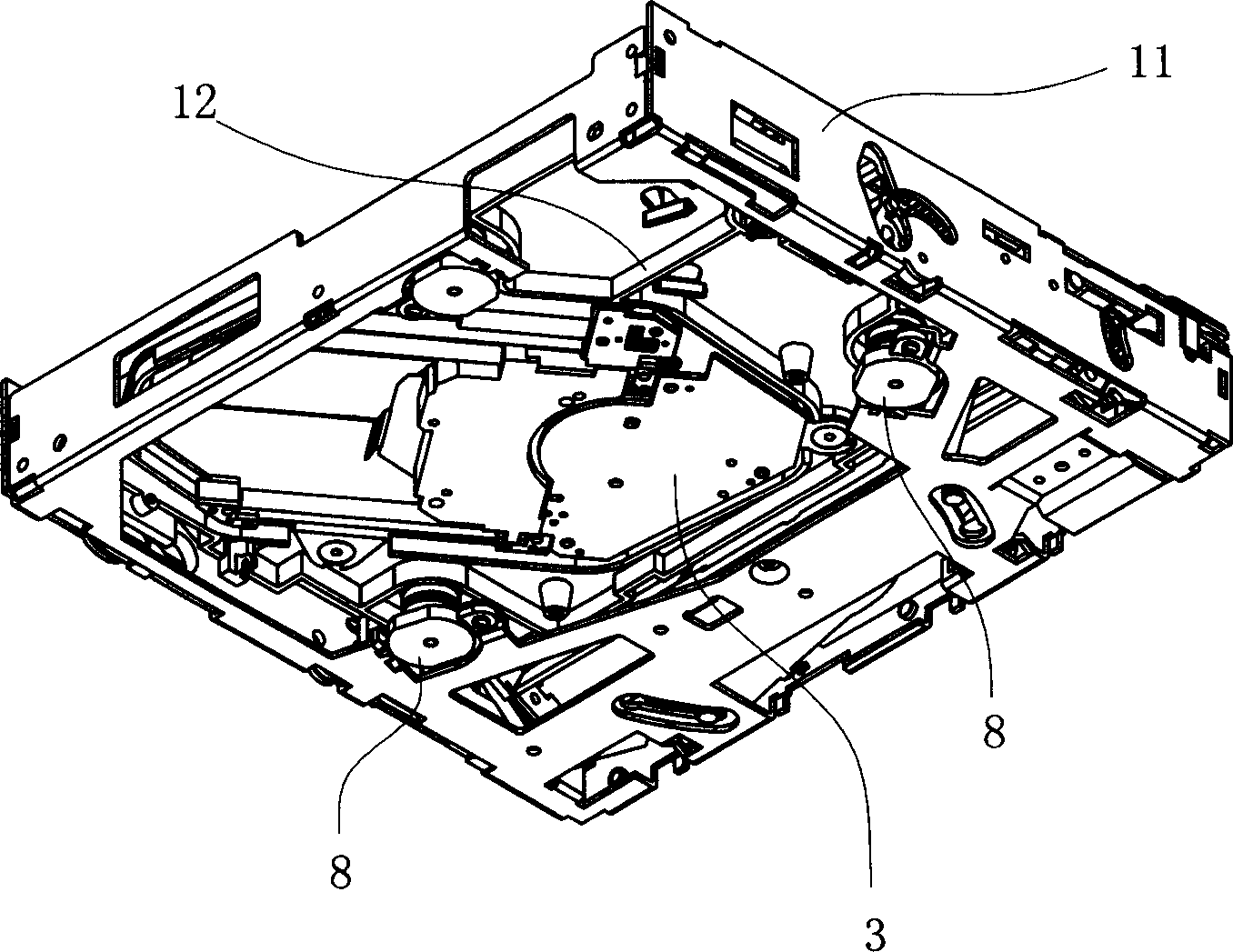
[0069] See Figures 10 to 21 and Figure 25 , Figure 26 , the movement shock-absorbing device of suction-type disk loading device has 3 to 4 groups of shock-absorbing assemblies 8, base 11 and optical pick-up drive part 3; Each group of shock-absorbing assemblies 8 has a shock-absorbing pad 81 respectively; The movement The shock absorber also has a mount 12; the base of the optical pickup driving part 3 is provided with 3 to 4 mounting feet 31, and each mounting foot 31 is provided with a mounting hole; the mount 12 is a plastic integral part, and the middle part is provided with The middle space that matches with the optical pickup driving part 3 through up and down; the installation base 12 is provided with the same mounting column 12-7 with the same number of mounting feet on the base of the optical pickup driving part 3 around the middle space; The mounting base 12 is also...

Embodiment 3

[0072] (Embodiment 3, Suction Type Disk Loading Device)

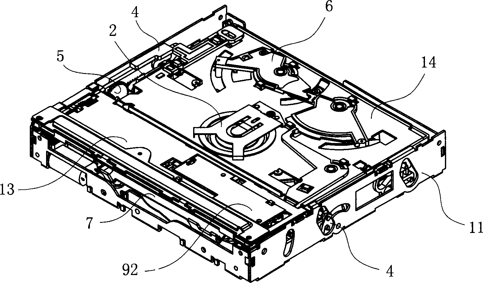
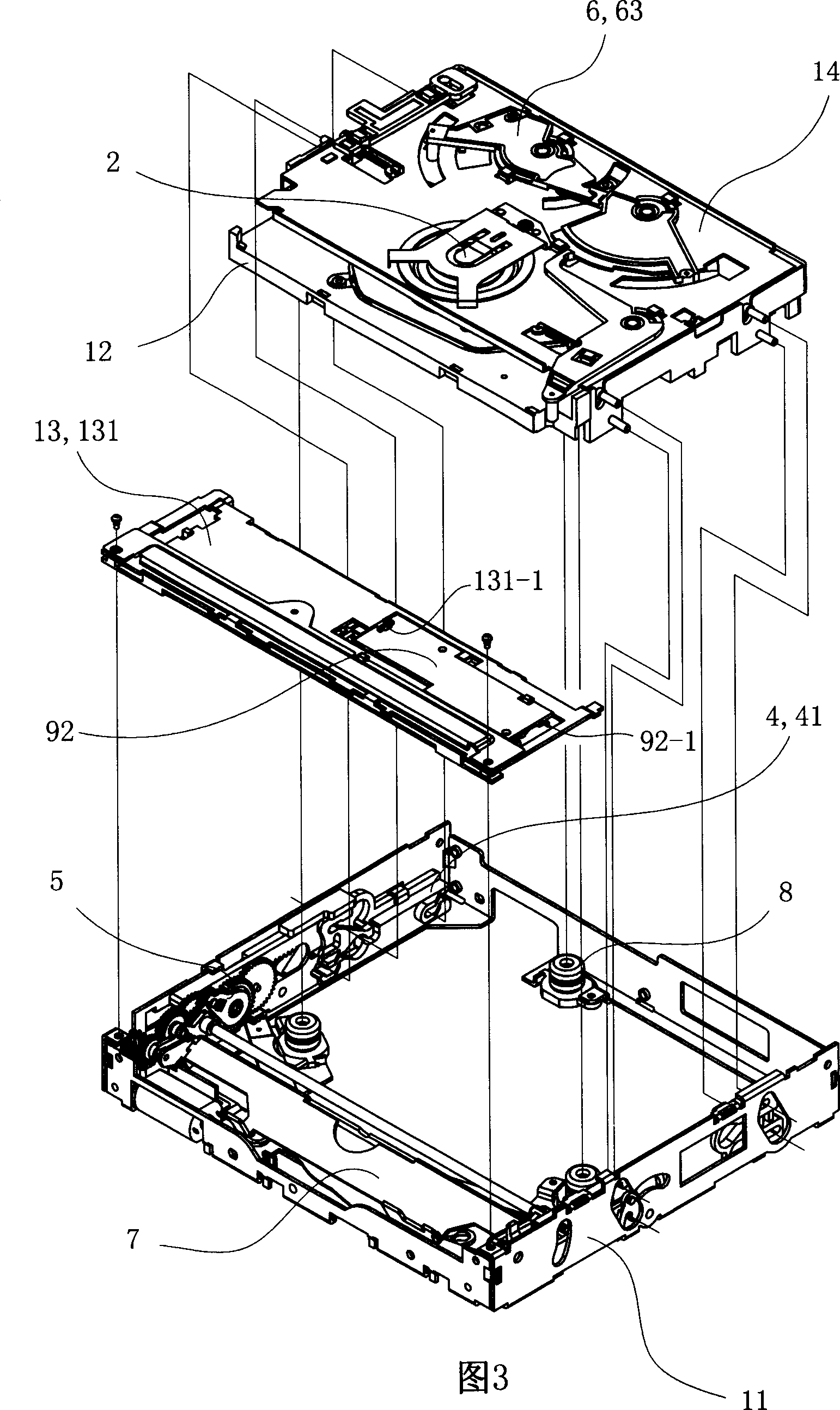
[0073] See Figure 1 to Figure 2 , The suction disk loading device has a base 11, a platen assembly 13, a control assembly 4, a transmission assembly 5, a guide roller assembly 7, a platen assembly 2, an optical pickup driving part 3 and 3 to 4 groups of shock absorbing assemblies 8.

[0074] See Figure 12 , The optical pickup driving part 3 is provided with a base, and the base is provided with 3 to 4 mounting feet 31, and each mounting foot 31 is provided with a mounting hole.

[0075] See Figure 25 and Figure 26, the base 11 has a front side plate 111, a rear side plate 112, a left side plate 113, a right side plate 114 and a bottom plate 115; the front part of the base 11 is provided with a guide roller assembly mounting part 116 with an upward installation direction, and the guide roller assembly The installation part 116 has the left guide roller shaft groove 116-1 with the opening upwards arranged on the l...


PUM


Abstract

A disc loading device of suction type consists of base, plate pressing component, control component, driving component, guiding roller component, disc pressing component, driving unit of light pick-up, three or four sets of shock absorption components formed by shock-absorbing pad and shock-absorbing connection seat as well as two shock-absorbing connection heads, erection base being connected to pick-up driving unit and to base of said loading device, support plate, coupling mechanism of optical disc, the first circuit board and the second circuit board.

Description

technical field [0001] The invention relates to a disk loading device, a movement shock absorbing device and components. Background technique [0002] The suction type disk loading device usually has a base part, a guide roller assembly, a transmission mechanism, a control assembly, an optical pickup drive part, an anti-vibration connection assembly, a pressure plate assembly, a disk insertion detection device, and a rotary dial; the suction type disk loading device uses It is controlled by the control circuit of the host. The Chinese patent application document with the application number 03132352 discloses an automatic suction-type disk loading device. The structure of the suction-type disk loading device is: its optical pickup drive part is elastically arranged in the base part through a shock-proof connection assembly, and is formed by The control component controls it to be in the suspended state where the disc can be loaded or in the locked state where the disc is lim...

Claims


Application Information

Patent Timeline
Patent Type & Authority Applications(China)
IPC IPC(8): G11B33/08G11B17/04
Inventor 谈捷沈军建嵇一平
Owner CHANGZHOU SHINCO AUTOMOTIVE ELECTRONICS
Learn More