
Vehicle motion control apparatus

A motion control, vehicle braking technology, applied to vehicle components, control valves and air release valves, brake components, etc., to solve problems such as high average speed, reduced accumulator hydraulic pressure, and increased wheel cylinder hydraulic pressure.

Inactive Publication Date: 2006-11-22
ADVICS CO LTD
View PDF1 Cites 8 Cited by
  • Summary
  • Abstract
  • Description
  • Claims
  • Application Information

AI Technical Summary

Problems solved by technology

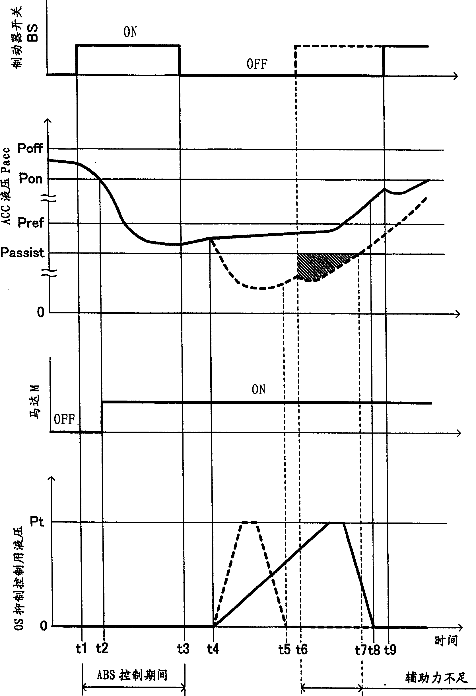
[0006] However, in the case where the increase or decrease of the wheel cylinder hydraulic pressure in the ABS control is extremely large and its cycle is short, or in the case where the ON-OFF cycle of the brake operation is extremely short in the pumping brake operation, the braking The average velocity of brake fluid in the hydraulic circuit returning to the tank (hereinafter referred to as "brake fluid consumption rate") becomes extremely fast
When the brake fluid consumption rate is extremely fast as described above, the accumulator hydraulic pressure decreases even if the hydraulic pump is continuously driven, and as a result, a phenomenon in which the accumulator hydraulic pressure decreases to a value close to the assist limit value may occur
[0007] When automatic pressurization control is activated with the accumulator hydraulic pressure decreasing to a value close to the assist limit value, there may be cases where the accumulator hydraulic pressure decreases even though the hydraulic pump is driven continuously because the brake fluid is supplied to the Wheel cylinders to increase wheel cylinder hydraulic pressure
As a result, the accumulator hydraulic pressure may be less than the auxiliary limit

Method used


Image

  • Vehicle motion control apparatus
  • Vehicle motion control apparatus
  • Vehicle motion control apparatus

Examples


no. 2 example

[0115] A vehicle braking apparatus including a vehicle motion control apparatus according to a second embodiment of the present invention will be described below. This second embodiment differs from the first embodiment in that, instead of using the hydraulic booster HB that assists the driver's braking operation by using the accumulator hydraulic pressure Pacc, brake-by-wire (brake-by-wire) is performed by using the accumulator hydraulic pressure Pacc. by-wire) control. The brake-by-wire control is used to generate the wheel cylinder hydraulic pressure Pw based on the signal output from the brake operation signal output device ** , wherein the brake operation signal output device outputs a signal (electrical signal) corresponding to the driver's brake operation, corresponding to the relevant signal (ie, corresponding to the driver's brake operation). Therefore, the difference will be mainly explained below. In the description of the second embodiment, components, variables,...


PUM


Abstract

This apparatus is applied to a vehicle brake apparatus provided with a hydraulic booster operated by utilizing an accumulator hydraulic pressure that is adjusted to a predetermined high pressure (not less than a lower limit value) by a drive control of a hydraulic pump. This apparatus executes an automatic pressurization control by controlling plural solenoid valves with the use of the accumulator hydraulic pressure. The increasing slope of the brake hydraulic pressure during the automatic pressurization control is determined on the basis of the vehicle motion state. The increasing slope is restricted to be not more than a predetermined restriction value, in case where the accumulator hydraulic pressure at the time of starting the automatic pressurization control is less than 'a reference hydraulic pressure that is greater than a minimum value of the accumulator hydraulic pressure necessary for assisting the brake operation by the hydraulic booster and smaller than the lower limit value'.

Description

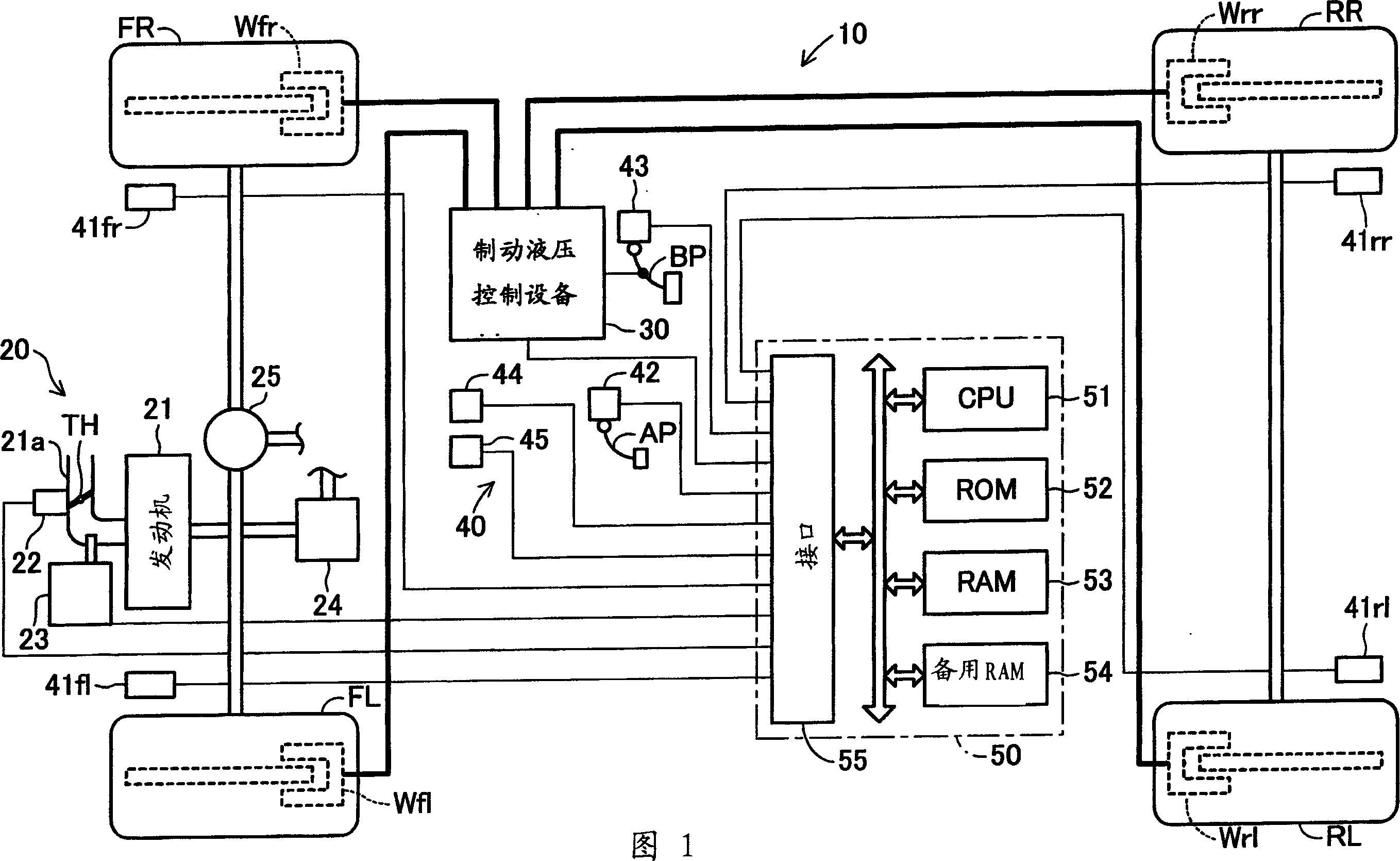
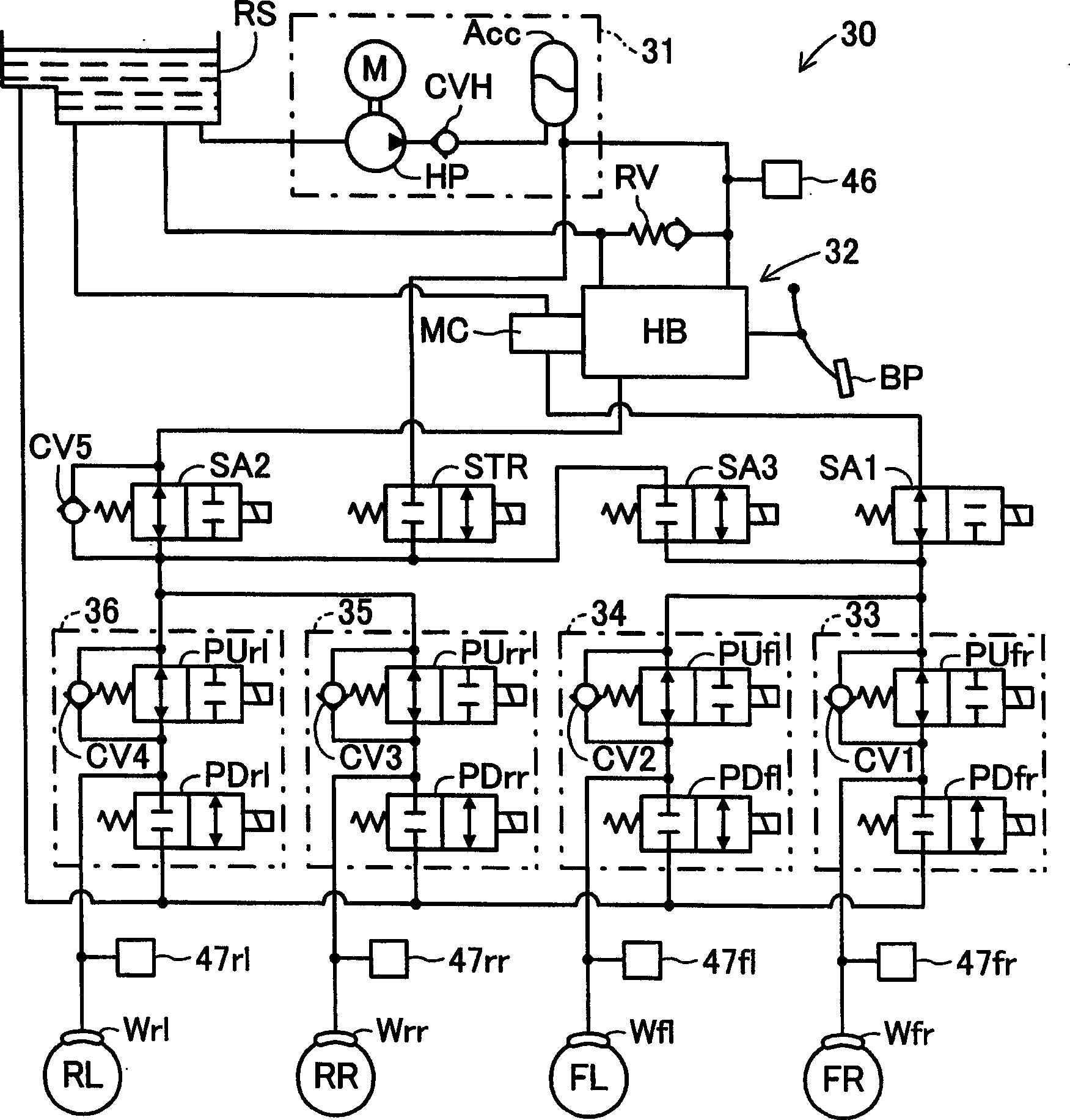
technical field [0001] The present invention relates to a vehicle motion control apparatus that performs automatic pressurization control to generate wheel cylinder hydraulic pressure to control vehicle motion independently of a driver's braking operation by utilizing accumulator hydraulic pressure. Background technique [0002] Conventionally, brake equipment is provided with a hydraulic pump, a motor for driving the hydraulic pump, a pressure accumulator for storing brake fluid (the pressure of the brake fluid is increased by driving the hydraulic pump driven by the motor), A hydraulic pressure booster (see, for example, Japanese Unexamined Patent Application No. 2004-066941) that assists the driver's brake pedal operation with the brake fluid pressure in the accumulator (hereinafter referred to as "accumulator hydraulic pressure"), which has become widely known to the public. [0003] The apparatus disclosed in the above reference is used to drive the motor (respectively...

Claims


Application Information

Patent Timeline
Patent Type & Authority Applications(China)
IPC IPC(8): B60T8/34
Inventor 西尾彰高矢野达也小岛诚一竹内清人田中博久
Owner ADVICS CO LTD
Learn More