Light emitting tube array type display unit and driving method thereof

A technology of a display device and a driving method, which is applied to alternating current plasma display panels, discharge tubes, identification devices, etc., can solve the problems of high discharge voltage, high shading rate, and deviation of discharge starting voltage, and achieves reduction in number and shading rate. , the effect of reducing the discharge voltage

Inactive Publication Date: 2006-11-08
SHINODA PLASMA
View PDF3 Cites 0 Cited by
  • Summary
  • Abstract
  • Description
  • Claims
  • Application Information

AI Technical Summary

Problems solved by technology

[0007] But in the arc tube array with this electrode layout, since the display discharge is set as a surface discharge, a higher discharge voltage is required
Also, the fluorescent layer is formed on the rear surface side inside the arc tube, and since the region of the surface discharge is separated from the above-mentioned fluorescent layer, the vacuum ultraviolet rays used for excitation cannot be sufficiently supplied to the fluorescent layer.
Also, since two display electrodes are placed at a single light emitting region on the front surface side of the arc tube array, the light shielding rate becomes high, resulting in low light emitting efficiency
[0008] Furthermore, due to irregularities caused by deviations in the tube diameter, etc., of the arc tube, insufficient adhesion between the display electrodes and the arc tube tends to occur, causing a deviation in the discharge start voltage for each light emitting area, resulting in failure to guarantee a higher Large operating margin and other issues

Method used


Image

  • Light emitting tube array type display unit and driving method thereof
  • Light emitting tube array type display unit and driving method thereof
  • Light emitting tube array type display unit and driving method thereof

Examples


Embodiment Construction

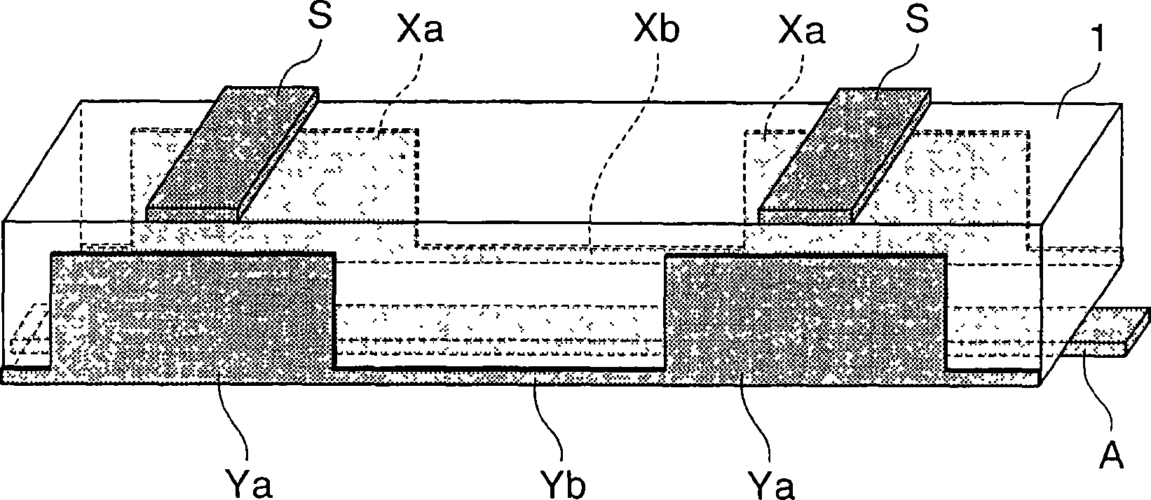
[0032] In the arc tube array type display device of the present invention, any type of arc tube array can be used as long as it has a structure in which a plurality of arc tubes are arranged side by side, and each arc tube has an arc tube sealed therein. discharge gas. As the thin tube forming the body of the arc tube, any thin tube having any diameter may be used, and those made of glass having a diameter ranging from 0.5 to 5 mm are preferably used. As for the shape of the thin tube, any cross-sectional shape such as a circular cross-section, an elliptical cross-section, and a rectangular cross-section can be used.

[0033]As the supporting member, any member may be used as long as it is brought into contact with at least one of the display surface side and the rear surface side of the arc tube array and it can support the arc tube array. For example, both a film made of resin and a substrate made of glass can be used as the supporting member. As the film made of resin, fo...


PUM


Abstract

A light emitting tube array type display unit comprising a light emitting tube array having juxtaposed a plurality of light emitting tubes each filled with a discharge gas thereinside, a support for supporting the light emitting tube array by being in contact with at least one of the display surface side and the rear surface side of the light emitting tube array, a plurality of display electrodes disposed at adjoining portions between light emitting tubes, for applying voltage to each light emitting tube from the opposite-side surfaces to generate counter discharge inside each light emitting tube, a plurality of scan electrodes disposed in a stripe form on the display surface side of the light emitting tubes in a direction crossing the lengthwise direction of the light emitting tubes to form light emitting regions at the intersections with light emitting tubes, and a plurality of address electrodes each disposed on the rear surface side of each light emitting tube, for selecting light emitting regions.

Description

technical field [0001] The present invention relates to an arc tube array type display device and a driving method thereof, and more particularly to an arc tube array type display device in which a plurality of arc tubes (also called are "display tube" and "gas discharge tube") aligned parallel to each other to display the desired image, each arc tube is formed of a thin tube with a diameter of about 0.5 to 5 mm, in which a phosphor layer is placed, and a discharge tube is sealed in it. gas. Background technique [0002] As for an arc tube array type display of this type, known are disclosed in Japanese Patent Application Laid-Open No. 2003-86141 and Japanese Patent Application Laid-Open No. 2003-86142. Figure 17 with 18 These examples are shown. Figure 18 yes Figure 17 is a partial cross-sectional view showing a state where the display device is cut in a direction perpendicular to the lengthwise direction of the arc tube of the display device. [0003] In this arc tub...

Claims


Application Information

Patent Timeline
Patent Type & Authority Applications(China)
IPC IPC(8): G09F9/313G09G3/20G09G3/28G09G3/288G09G3/291G09G3/292G09G3/293G09G3/294H01J11/12H01J11/16H01J11/18H01J11/24H01J11/26H01J11/32H01J11/36H01J11/38H01J11/40H01J11/42H01J11/50H01J11/54
CPCG09G3/2803G09G3/2927G09G3/294G09G3/2986G09G2310/066G09G2320/0228H01J11/18H01J11/24H01J11/32
Inventor 平川仁石本学粟本健司
Owner SHINODA PLASMA
Why Eureka
Try Eureka