Cast-in-place concrete hollow plate

A technology of cast-in-place concrete and hollow slabs, which is applied in the field of cast-in-place concrete hollow slabs, and can solve problems such as troublesome repair of the bottom surface of cast-in-place concrete hollow slabs

Inactive Publication Date: 2006-10-25
湖南邱则有专利战略策划有限公司
View PDF2 Cites 1 Cited by
  • Summary
  • Abstract
  • Description
  • Claims
  • Application Information

AI Technical Summary

Problems solved by technology

But this formwork component is in the cast-in-place concrete hollow slab, and the formed cast-in-place concrete hollow slab must be equipped with structural accessories such as fire sprinklers to prevent standby in case of a fire, but this is often done on the newly repaired site. It is very troublesome to repair the bottom surface of the cast-in-place concrete hollow slab after installation.

Method used


Image

  • Cast-in-place concrete hollow plate
  • Cast-in-place concrete hollow plate
  • Cast-in-place concrete hollow plate

Examples


Embodiment Construction

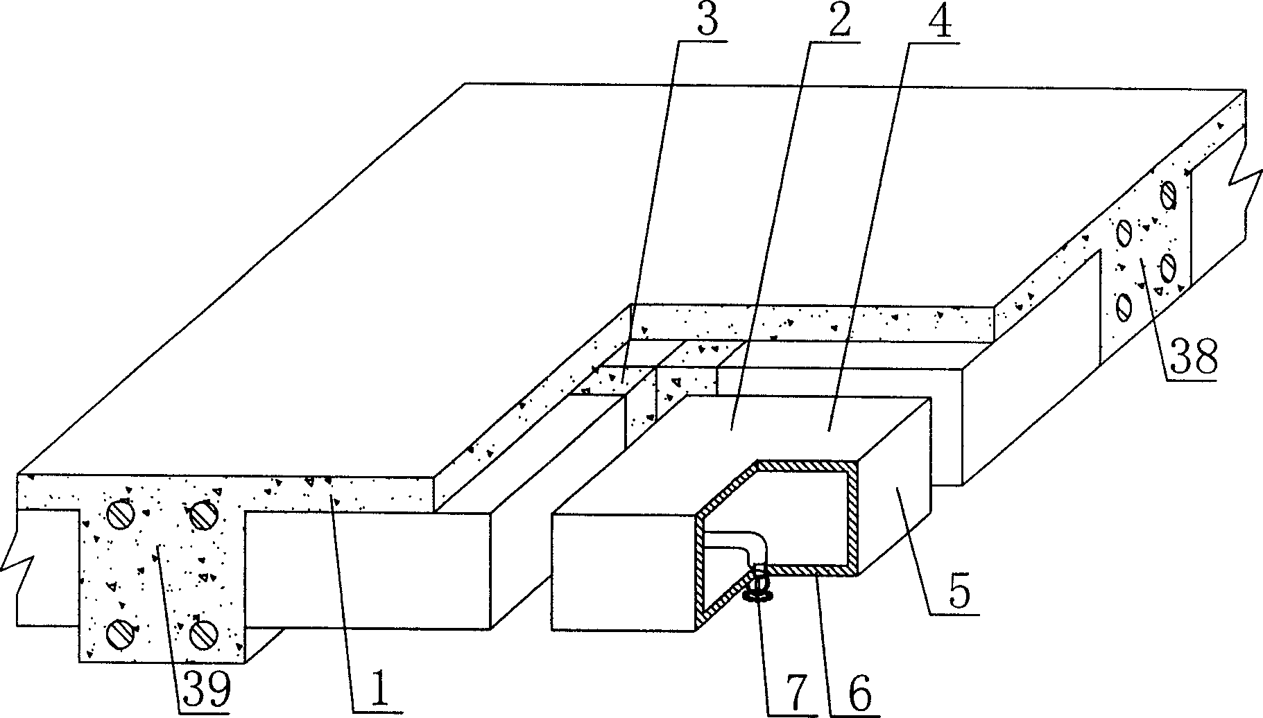
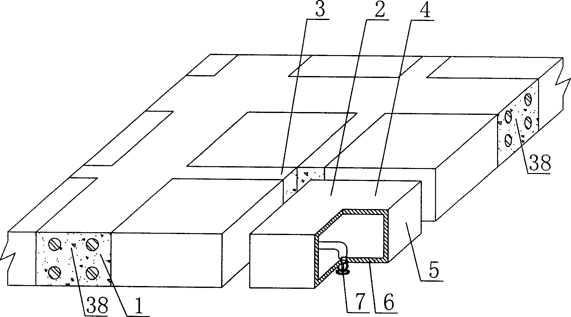
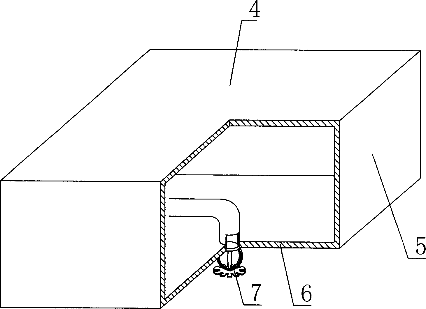
[0070] The present invention will be further described below in conjunction with the accompanying drawings and embodiments.

[0071] As shown in the accompanying drawings, the present invention includes reinforced concrete 1, formwork components 2, the formwork components 2 are wrapped in the reinforced concrete 1, the formwork components 2 are arranged alternately, and there are cast-in-situ reinforced concrete ribs 3 between each other, and the formwork The component 2 includes an upper plate 4, a surrounding side wall 5, and a lower bottom plate 6. The upper plate 4, the surrounding side walls 5, and the lower bottom plate 6 form a closed polyhedral cavity formwork member, which is characterized in that the lower bottom plate 6 is provided with There is at least one fire sprinkler head 7, and the bottom surface of the lower base plate 6 is flush with the bottom surface of the cast-in-place concrete hollow slab. In the drawings, 1 is reinforced concrete, 2 is formwork compon...


PUM


Abstract

The invention is a cast-in-site concrete hollow slab, comprising reinforced concrete and form components, where the form components are wrapped in the reinforced concrete, and staggeredly arranged, cast-in-site reinforced concrete ribs are arranged between them, and each form component comprises top plate, peripheral side wall and infrabasal plate, which compose a closed polyhedral cavity form component, and it is characterized in that the infrabasal plate is provided with at least a fire sprinkler, and the bottom surface of the infrabasal plate is on the same plane with that of the cast-in-site hollow slab. And the invention is applied to cast-in-site reinforced concrete or prestressed reinforced concrete hollow floor systems, house covers, walls, foundation slabs and hollow bridges.

Description

(1) Technical field [0001] The invention relates to a cast-in-place concrete hollow slab. (2) Background technology [0002] At present, the cast-in-place concrete hollow slab is a widely used floor structure, and the lightweight permanent tire mold filled in it includes hollow tubes and cavity formwork components. For example, the patent No. ZL99249798.1, which the applicant applied for on November 29, 1999, is a utility model patent named "fiber-reinforced thin-walled member for reinforced concrete filling", which discloses a thin-walled formwork member, including an upper plate, The surrounding side walls, the lower bottom, and the upper plate, the surrounding side walls and the lower bottom form a polyhedral cavity. Another example is that the application number applied by the applicant on November 23, 2001 is 01140106.0, the publication number is CN1356442, and the name is called "a kind of cavity structure formwork for cast-in-place reinforced concrete floor slab" pat...

Claims


Application Information

Patent Timeline
IPC IPC(8): E04B1/16E04B5/36E04B5/48E04C5/00E04G15/06
Inventor 邱则有
Owner 湖南邱则有专利战略策划有限公司
Why Eureka
Try Eureka