Single-pipe heat distribution metering management network system for central heating and its charging method
A household metering and management network technology, applied in the field of centralized heating household metering system, can solve the problems of complex pipelines, high cost, and inability to control indoor temperature
- Summary
- Abstract
- Description
- Claims
- Application Information
AI Technical Summary
Problems solved by technology
Method used
Image

Examples
Embodiment 1
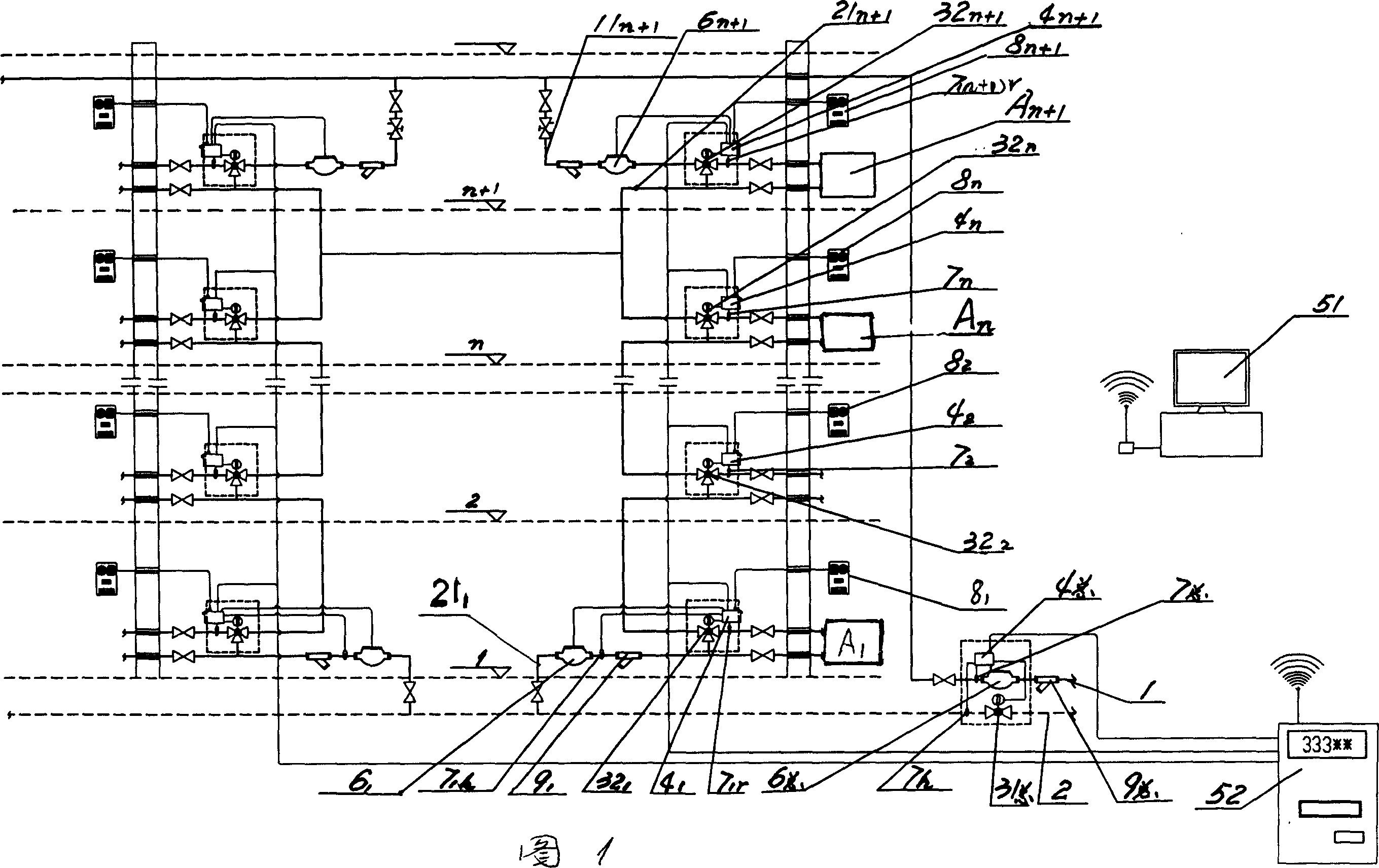
[0036] Example 1: As shown in Figure 1, the new single-pipe system is a centralized heating single-pipe heat distribution household metering management network system, and heating branch pipe 11 is set on the n+1 layer of the heating area n+1 , Set the return pipe 2 at its lower level; the heating branch pipe 11 of the n+1 layer n+1 ,Connect the heating load A of this floor n+1 , By the heating load A n+1 Backwater branch pipe 21 n+1 Connecting to the heating load A of the next floor n , Heating from top to bottom in turn, until the heating load A of the first layer 1 Backwater branch pipe 21 1 It is connected with the return pipe 2 at the lower level, and a remote flow meter 6 is installed on the heating main pipe 1. 总 And inlet water temperature sensor 7 总 , And there is an intelligent electric two-way flow proportional distribution stop valve 31 on the return pipe 2 总 And return water temperature sensor 7 h The control output terminal is connected to the master acquisition cont...
Embodiment 2
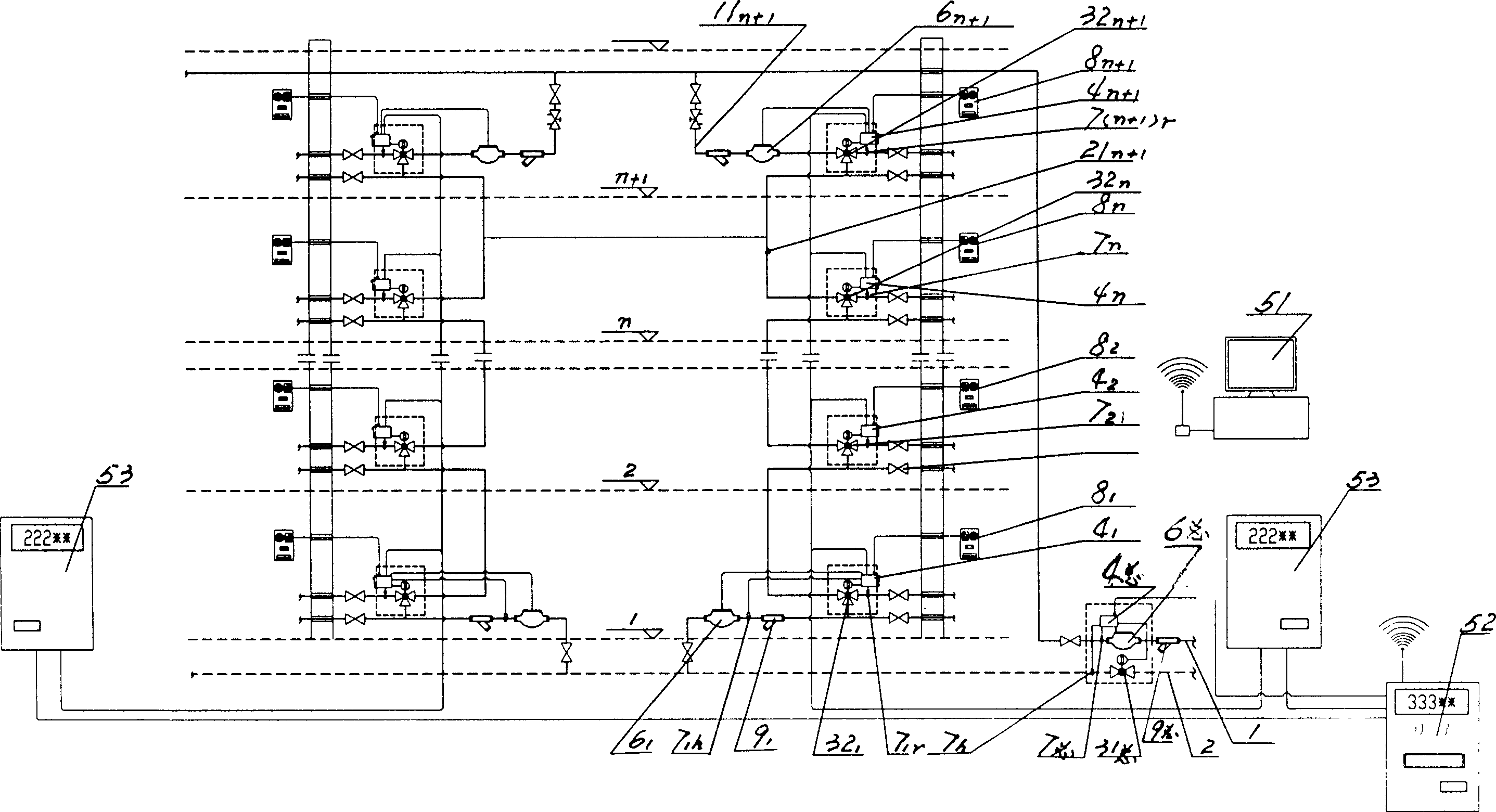
[0040] Example 2: See figure 2 , A new single-pipe system, the computer monitoring system 5 includes a regional heat distribution center computer platform 51 connected to multiple communities and a single building embedded real-time monitoring summary table 52, and its output is connected to multiple unit embedded real-time monitors 53, The output terminal of the embedded unit real-time monitor 53 is connected to the household acquisition controller 4 n . The rest of the structure is the same as the above example. There are also valves in the heating network.
Embodiment 3
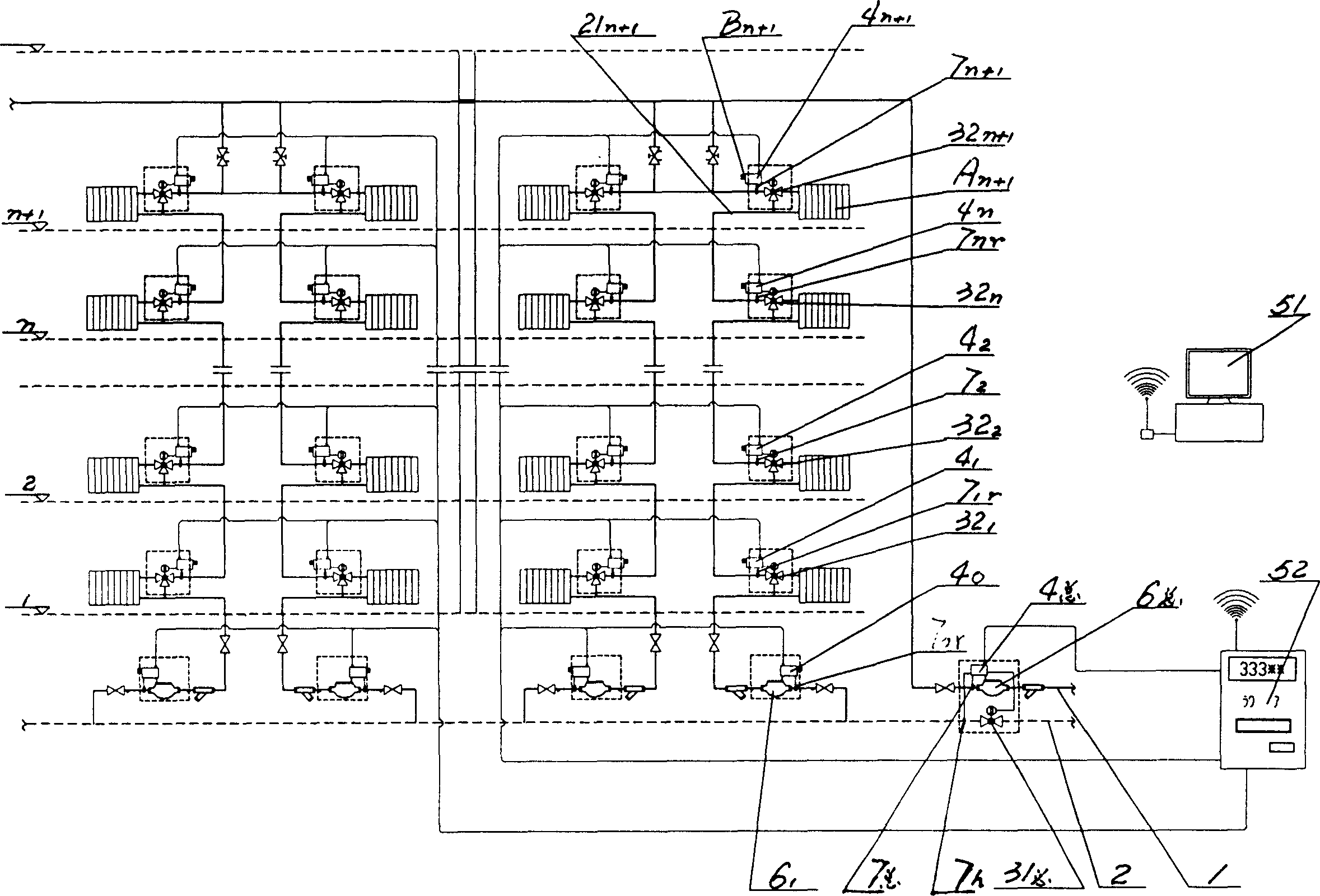
[0042] Example 3: See image 3 , The centralized heating single-tube heat distribution household metering and charging management network system for the transformation of the single-tube old system, including the setting of heating branch pipes 11 in the n+1 layer of the heating area n+1 ,Set the return pipe 2 at its lower level, which consists of n+1 layer heating branch pipes 11 n+1 ,Connect the heating load A of this floor n+1 . The load of the old single-tube system is the load of each room and the load of each heating load A n+1 Backwater branch pipe 21 n+1 Connect to the corresponding indoor heating load A of the next floor n , Heating from top to bottom in turn, until the heating load A of the first layer 1 Backwater branch pipe 21 1 It is connected with the return pipe 2 at the lower level, and a remote flow meter 6 is installed on the heating main pipe 1. 总 And inlet water temperature sensor 7 总 And there is an intelligent electric two-way flow adjustment shut-off valve 3...
PUM
 Abstract
Description
Claims
Application Information
 - Generate Ideas
- Intellectual Property
- Life Sciences
- Materials
- Tech Scout
- Unparalleled Data Quality
- Higher Quality Content
- 60% Fewer Hallucinations
Browse by: Latest US Patents, China's latest patents, Technical Efficacy Thesaurus, Application Domain, Technology Topic, Popular Technical Reports.
© 2025 PatSnap. All rights reserved.Legal|Privacy policy|Modern Slavery Act Transparency Statement|Sitemap|About US| Contact US: help@patsnap.com