Air feeder vane wheel
A blower and impeller technology, applied in the direction of mechanical equipment, machines/engines, liquid fuel engines, etc., can solve the problems of flow control noise improvement and fan efficiency improvement limitations
- Summary
- Abstract
- Description
- Claims
- Application Information
AI Technical Summary
Problems solved by technology
Method used
Image

Examples
Embodiment 1
[0035] refer to figure 1 , figure 2 , image 3 , Figure 7 , Figure 11 Example 1 of the present invention will be described.
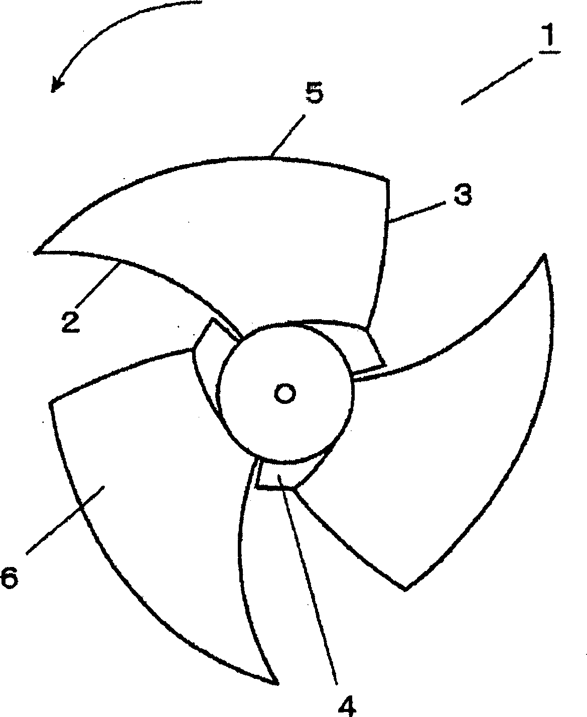
[0036] figure 1 It is a meridian view of the oblique flow fan impeller of the present invention. figure 2 It is a cross-sectional view in the radial direction of the impeller of the oblique flow blower according to the present invention. image 3 It is a plan view of the impeller of the oblique flow blower of the present invention. Figure 7 It is a perspective view of the impeller of the diagonal flow blower of the present invention. Figure 11 It is a schematic diagram of the operation state of the impeller of the diagonal flow blower of the present invention.
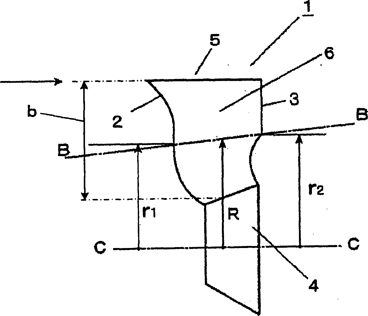
[0037] figure 1 Among them, the oblique flow blower impeller 1 of the present invention is constituted by setting a plurality of thin blades 6 on a substantially truncated cone-shaped hub 4, and the leading edge 2 of the blade 6 is formed in the following shape: on the meridian...
Embodiment 2
[0041] refer to figure 1 , Figure 4 , Figure 5 , Image 6 Example 2 of the present invention will be described.
[0042] figure 1 It is a meridian view of the oblique flow fan impeller of the present invention. Figure 4 It is a plan view of the impeller of the oblique flow blower of the present invention. Figure 5 It is the expanded view of the blade section of the oblique flow fan impeller of the present invention. Image 6 is the experimental data of aspect ratio and noise-air volume.
[0043] figure 1 , Figure 4 For the oblique flow blower impeller provided in , in the meridian plane of the blade 6, that is, the shape of the rotation track, the radius from the leading edge 2 to the midpoint of the hub 4 and the blade tip 5 is r1, and the radius from the trailing edge 3 to the hub 4 The radius from the midpoint of the blade tip 5 is r2, and the blade chord length in the cross-sectional developed shape of the flow path centerline B-B (the centerline connectin...
Embodiment 3
[0048] refer to figure 2 Embodiment 3 of the present invention will be described.
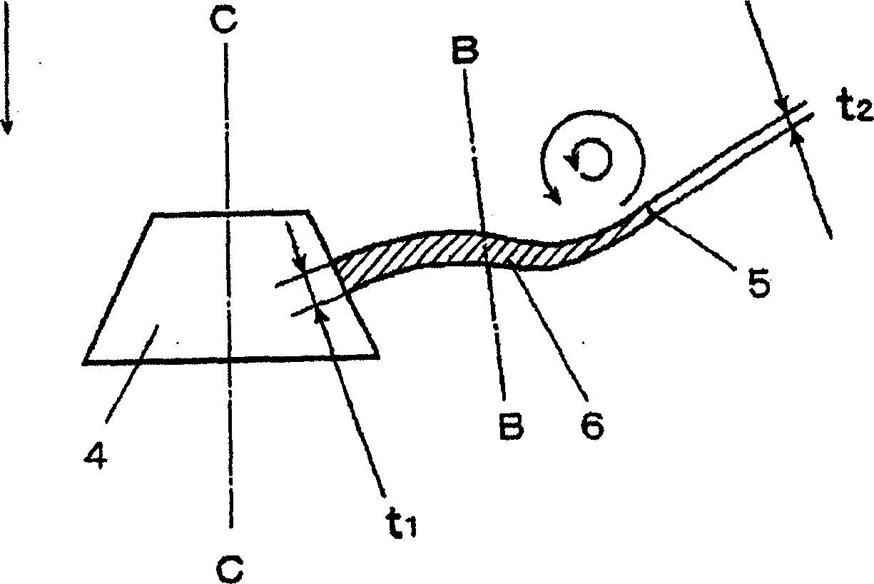
[0049] figure 2 It is a cross-sectional view in the radial direction of the impeller of the oblique flow blower according to the present invention.
[0050] exist figure 2 In the provided oblique flow blower impeller 1, the blade thickness of the blade 6 on the side of the hub 4 is t1, and the blade thickness of the blade tip is t2, and the dimensional relationship of t1>t2 is satisfied at this time.
[0051] Next, the operation and function of the impeller of the oblique flow blower constructed as above will be described.
[0052] When the oblique flow blower impeller 1 is made of resin, etc., because the relationship of t1>t2 is satisfied, the weight of the fan on the outer peripheral side is relatively small, so the centrifugal force added to the hub 4 is small, and even if the fan rotates at a high speed, it can also reduce partly broken from the hub 4 of danger. In the strength ana...
PUM
 Abstract
Description
Claims
Application Information
 - R&D
- Intellectual Property
- Life Sciences
- Materials
- Tech Scout
- Unparalleled Data Quality
- Higher Quality Content
- 60% Fewer Hallucinations
Browse by: Latest US Patents, China's latest patents, Technical Efficacy Thesaurus, Application Domain, Technology Topic, Popular Technical Reports.
© 2025 PatSnap. All rights reserved.Legal|Privacy policy|Modern Slavery Act Transparency Statement|Sitemap|About US| Contact US: help@patsnap.com