In-situ cast hollow concrete slab

A technology of cast-in-place concrete and hollow slabs, which is applied in the field of cast-in-place concrete hollow slabs, and can solve the problems of poor earthquake resistance, poor mechanical properties of cast-in-place concrete hollow slabs, and large consumption

Inactive Publication Date: 2006-10-18
湖南邱则有专利战略策划有限公司
View PDF1 Cites 1 Cited by
  • Summary
  • Abstract
  • Description
  • Claims
  • Application Information

AI Technical Summary

Problems solved by technology

After this kind of thin-walled pipe is applied to the cast-in-place concrete hollow slab, since the thin-walled pipes actually used are circular thin-walled pipes, the amount of reinforced concrete for the cast-in-place concrete hollow slab is large and the weight is large, and the corresponding cast-in-place concrete hollow slab Poor mechanical properties and poor shock resistance, therefore, it is urgently needed to develop a new type of cast-in-place concrete hollow slab

Method used


Image

  • In-situ cast hollow concrete slab
  • In-situ cast hollow concrete slab
  • In-situ cast hollow concrete slab

Examples


Embodiment Construction

[0075] The present invention will be further described below in conjunction with the accompanying drawings and embodiments.

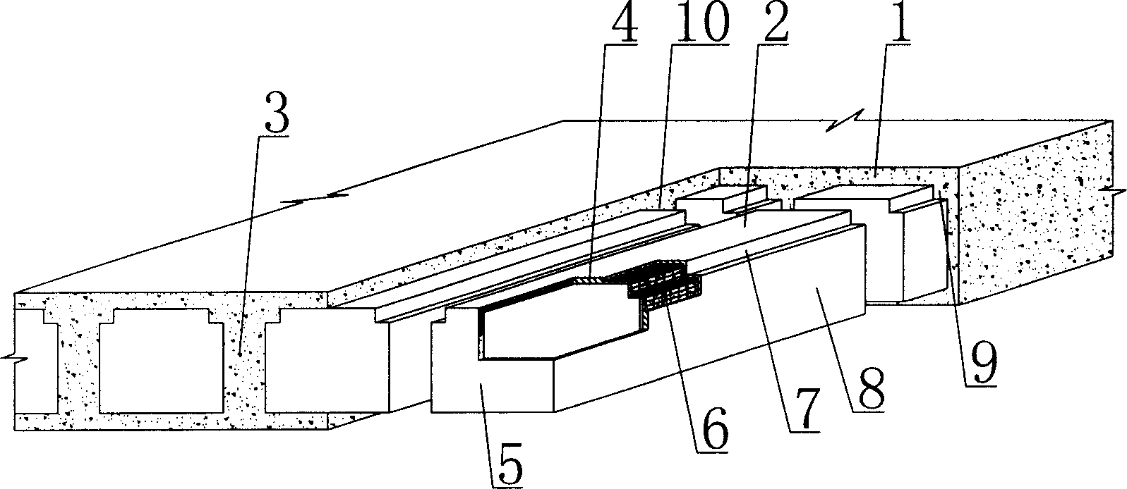
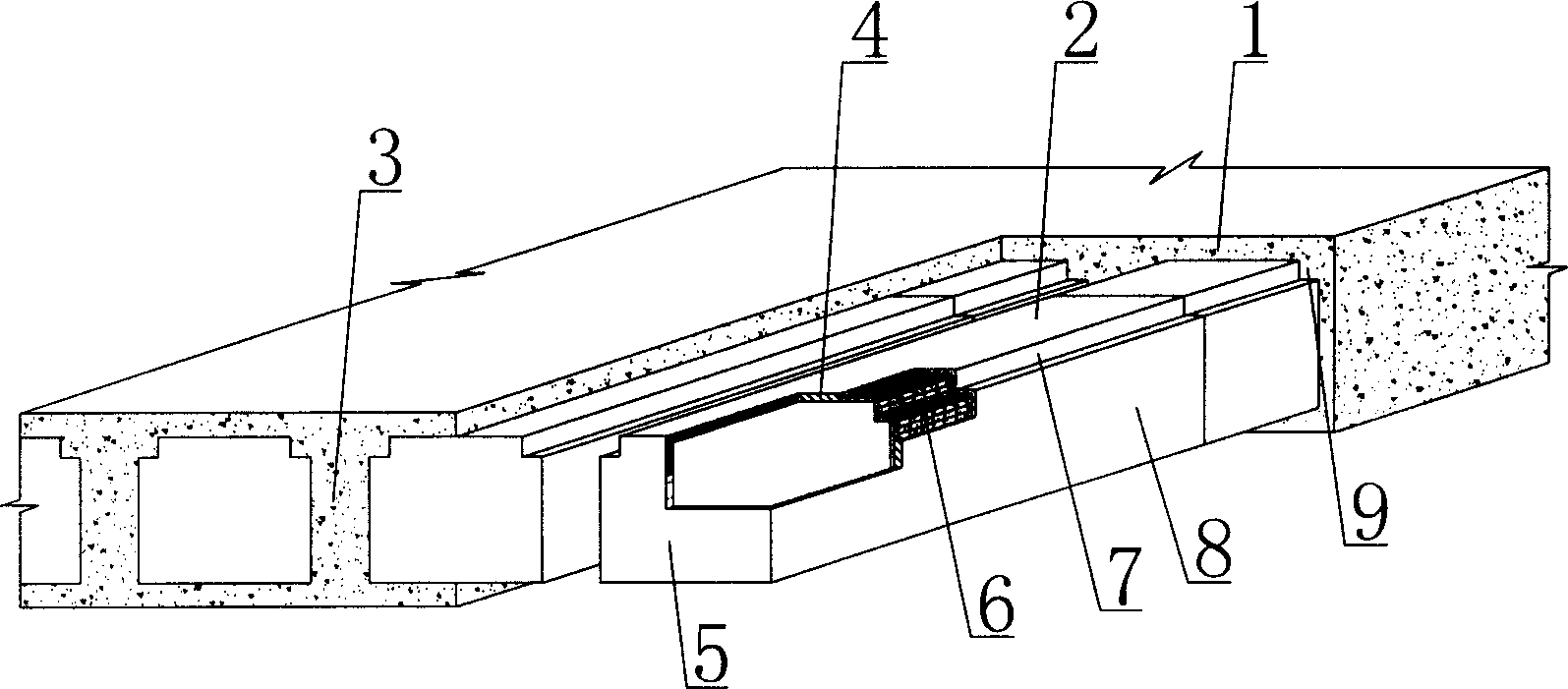
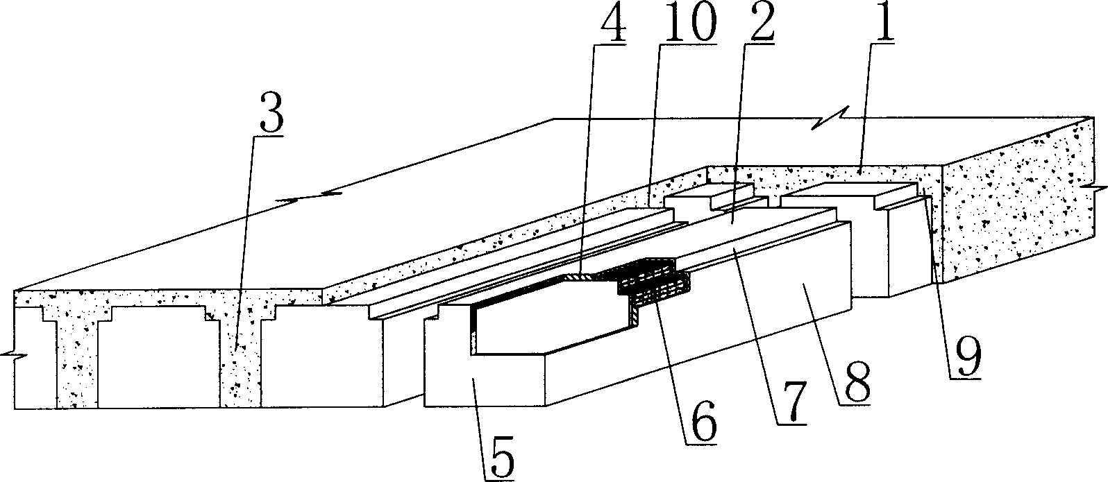
[0076] As shown in the accompanying drawings, the present invention includes reinforced concrete 1 and thin-walled pipes 2. The thin-walled pipes 2 are wrapped in the reinforced concrete 1. Cast-in-place reinforced concrete ribs 3 are arranged between the thin-walled pipes 2 along the longitudinal direction of the pipes. The wall tube 2 includes a hollow tube body 4 and a plug 5. The plugs 5 at both ends close the two ends of the hollow tube body 4 to form a thin-walled tube with a closed cavity. At least one of the hollow tube body 4 and the plug 5 contains a reinforcement 6. It is characterized in that the cross-sectional shape of the hollow pipe body 4 is a quadrilateral, at least one corner of which is an inner corner 7, at least one surface 8 of the hollow pipe body 4 is planar or nearly planar, and the cast-in-place concrete The cast-in-place conc...


PUM


Abstract

The in-situ cast hollow concrete slab includes reinforced concrete and thin wall pipes wrapped inside the concrete. There are longitudinal in-site cast reinforced concrete ribs between the thin wall pipes. Each of the thin wall pipes includes hollow pipe and end plugs to close the ends of the hollow pipe to form closed cavity. At least one of the hollow pipe and the end plugs has reinforcement. The present invention features that the hollow pipe has quadrilateral cross section, at least one reentrant corner and at least one plane, the in-situ cast concrete forms flange in the reentrant corner while the in-situ reinforced concrete ribs are T-shpaed or I-shaped ribs. The present invention is suitable for use in various kinds of in-situ cast or pre-stressed reinforced concrete hollow floor slab, roof, wall, foundation slab and hollow bridge.

Description

(1) Technical field [0001] The invention relates to a cast-in-place concrete hollow slab. (2) Background technology [0002] At present, in the existing technology, the hole-forming components of cast-in-place concrete hollow slabs are permanent mandrels, such as paper tubes, plastic tubes, metal bellows, and lightweight materials for mandrels. These tubular mandrels or components are mainly considered to evacuate concrete. Reduce the weight of cast-in-place concrete hollow slabs. For example, the patent number applied by the applicant is ZL99249755.8, and the name is a utility model patent named "fiber-reinforced thin-walled cylinder for filling cast-in-place reinforced concrete". It includes a hollow pipe body and a plug. The end is closed to form a thin-walled tube with a closed cavity, and at least one of the hollow tube body and the plug contains reinforcements such as fibers. After this kind of thin-walled pipe is applied to the cast-in-place concrete hollow slab, si...

Claims


Application Information

Patent Timeline
IPC IPC(8): E04B1/16E04B2/84E04B5/36E04C5/00E04G15/06
Inventor 邱则有
Owner 湖南邱则有专利战略策划有限公司
Why Eureka
Try Eureka