Touch type induction device

A sensing device and touch-type technology, applied in mechanical mode conversion, instrumentation, electrical digital data processing, etc., can solve problems such as large EMI, increased software judgment complexity, and circuit complexity

Active Publication Date: 2006-10-11
HONG FU JIN PRECISION IND (SHENZHEN) CO LTD +1
View PDF3 Cites 39 Cited by
  • Summary
  • Abstract
  • Description
  • Claims
  • Application Information

AI Technical Summary

Problems solved by technology

[0009] The above-mentioned traditional technology uses a single signal source input, which generates large EMI (ElectroMagnetic Interference) and leakage current, and each sensor 11 needs to correspond to a detector 13, making the circuit more complicated, and determining which sensor 11 is used When touching, the sensing device needs to be scanned at regular intervals, which increases the complexity of software judgment

Method used


Image

  • Touch type induction device
  • Touch type induction device
  • Touch type induction device

Examples


Embodiment Construction

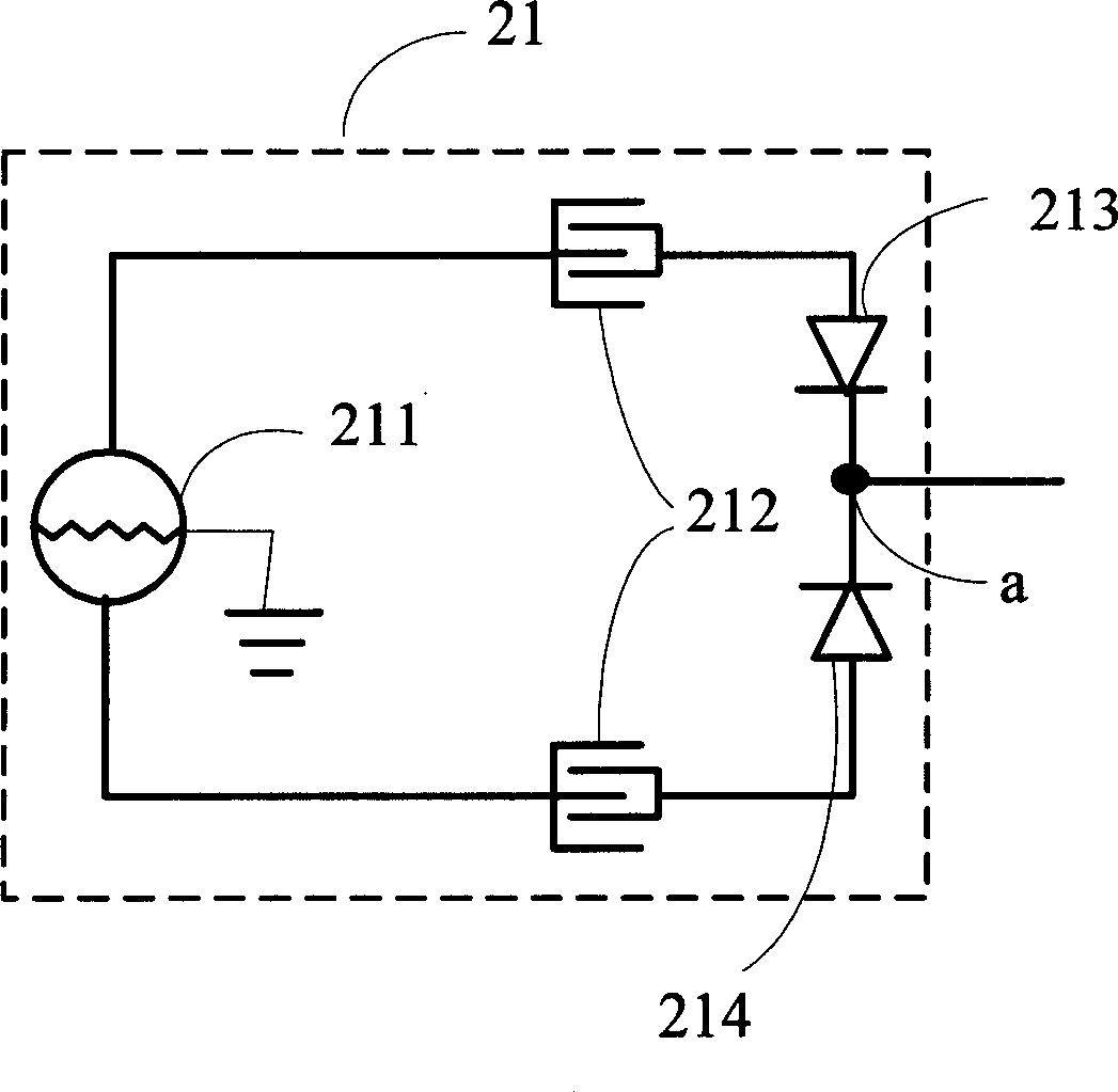
[0017] see figure 2 , is a circuit diagram of each sensing unit of an embodiment of the touch sensing device. The touch sensing unit 21 includes a differential signal source 211 , two sensors 212 , a first diode 213 and a second diode 214 . The differential signal source 211 is used to generate two signals with the same frequency but opposite polarities, so that electromagnetic interference (EMI) can be reduced; two inductors 212 are used to receive the signals generated when objects are in contact, and make the Signals are transmitted through the inductors, one of which is connected to the positive signal output terminal of the differential signal source, and the other is connected to the negative signal output terminal of the differential signal source; the first diode 213 and the second The anodes of the diodes 214 are respectively connected to an inductor 212, which is used to prevent the leakage current generated by the sensing unit 21 from forming a closed loop, thereb...


PUM


Abstract

The invention discloses a touch sensor, which comprises: at least one sensing unit, one detector, one signal processing unit, and one reference signal circuit. Wherein, said sensing unit comprises a differential signal source for generating two signals with reversed polarities; two sensors while one is connected to the positive output of differential signal source and another sensor is connected to the negative output; said detector is connected to several sensing units to transform received signal into digital signal; the signal processing unit is connected to the output of detector, to find the sensor that contacted by object according to the frequency and phase of digital signal output by detector. The invention can reduce electromagnetic disturbance and current leakage, reduce the circuit complexity, and quick find touched position.

Description

【Technical field】 [0001] The invention relates to a touch sensing device, in particular to a sensing device for identifying target positions through the phase and frequency of input signals. 【Background technique】 [0002] Various types of sensing devices exist and are used in computer systems and other applications, the most familiar of which is the computer "mouse". Although the mouse is extremely common as a position-pointing device, it has mechanical parts and requires a flat surface on which the position ball can roll, and, in order to have a reasonable resolution, the mouse usually needs to roll a long distance. Finally, the mouse needs The user raises his hand to cause the cursor to move, thereby interfering with the main purpose of people typing from a computer. [0003] Various attempts have been made to provide a means for detecting the position of a thumb or other finger used as a pointing device instead of a mouse, the desirable characteristics of which are low ...

Claims


Application Information

Patent Timeline
Patent Type & Authority Applications(China)
IPC IPC(8): G06F3/033G06K11/06
CPCG06F3/044
Inventor 谢冠宏林世权王汉哲李晓光
Owner HONG FU JIN PRECISION IND (SHENZHEN) CO LTD
Why Eureka
Try Eureka