Gasifying furnace nozzle
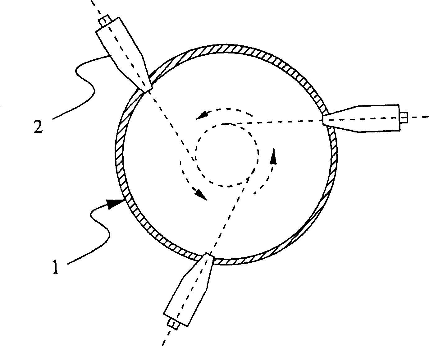
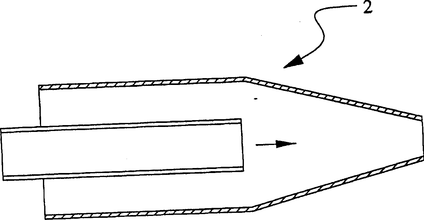
A gasifier and nozzle technology, which is applied to injection devices, injection devices, etc., can solve the problems of reducing gasification efficiency, increasing fuel mixing time, and uneven injection of pulverized coal.
- Summary
- Abstract
- Description
- Claims
- Application Information
AI Technical Summary
Problems solved by technology
Method used
Image
Examples
Embodiment 1
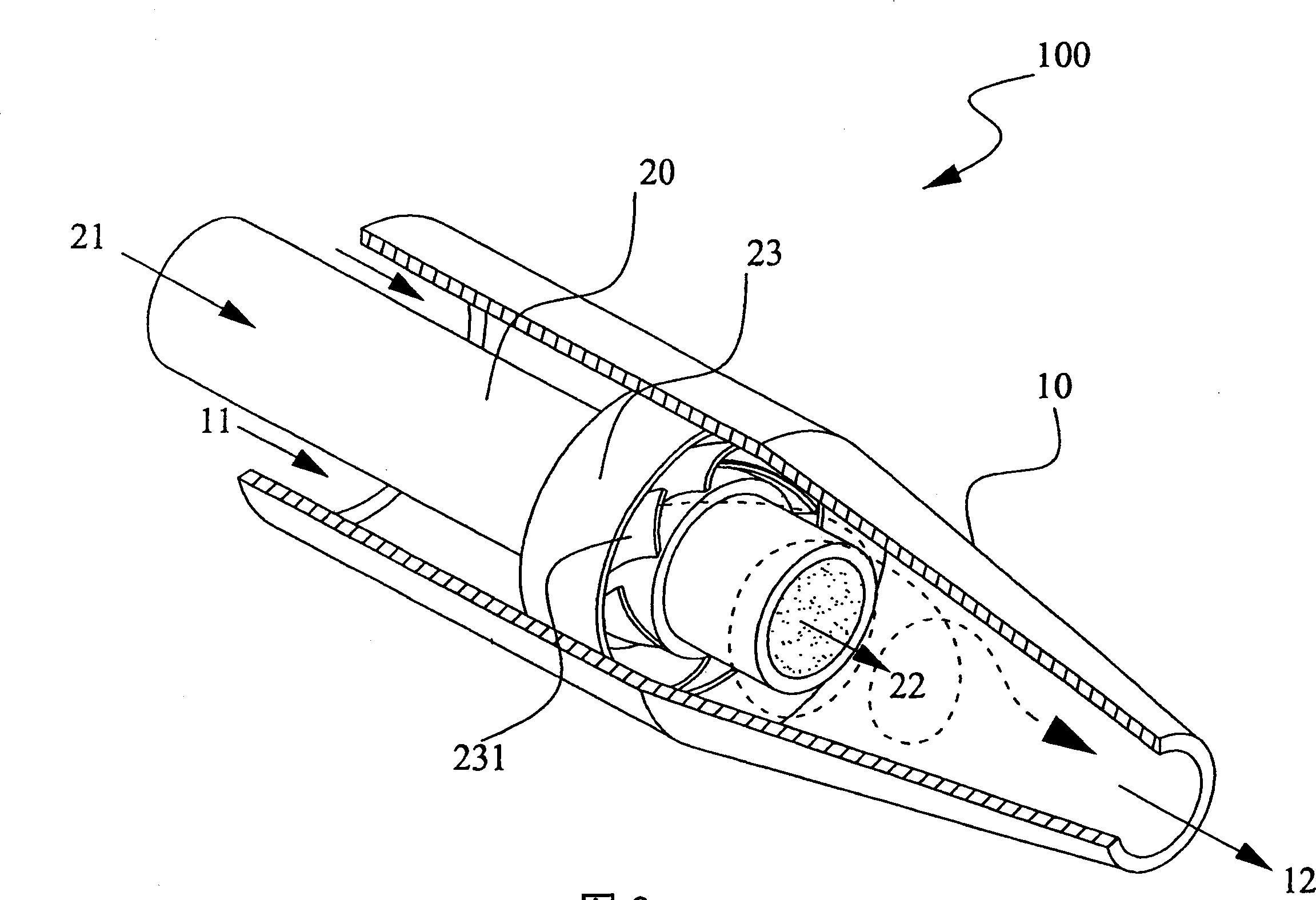
[0016] Please refer to image 3 , is a preferred schematic diagram of the gasifier nozzle 100 of the present invention, and the nozzle 100 includes: an outer casing 10 and an inner casing 20 . The outer casing 10 has an air inlet 11 and a nozzle 12, the inner casing 20 has a feed inlet 21 and an outlet 22, and the inner casing 20 can include at least one vortex generating device 23 mounted on the inner casing 20 on the pipe wall. Wherein, the diameter of the nozzle 12 of the outer sleeve 10 is smaller than the diameter of the air inlet 11 ;
[0017] In the present embodiment, the air inlet 11 of the outer sleeve 10 can provide combustible or combustion-supporting gas; the feed inlet 21 of the inner sleeve 20 can provide solid fuel; Rotate, thereby forming a vortex gas.
[0018] In addition, the diameter of the inner casing inlet 21 in this embodiment is equal to the diameter of the outlet 22, and the vortex generating device 23 in this embodiment may include a set of fixed ...
Embodiment 2
[0022] Another preferred embodiment of this experiment is the same as the gasifier nozzle 100 of Embodiment 1, except that in the vortex generating device 23, a set of rotating helical blades 231 can be included, and the rotating helical blades 231 can also be Arranged around the inner tube wall. The rotary helical blade set 231 used in this embodiment is rotated by an electric motor.
Embodiment 3
[0024] A more preferred embodiment of this experiment is to use the gasifier nozzle 100 of Embodiment 1 in combination with a gasifier (not shown in the figure), which can promote solid fuel and combustible or combustion-supporting gas at the gasifier nozzle 100 The mixing chamber 30 inside is fully mixed, and then sent to the gasifier for reaction. The outer casing spout 12 of the gasifier nozzle 100 of the present invention can be connected with the inlet on the gasifier wall, and the mixed fuel can be ejected from the gasifier nozzle 100 from time to time to provide the reaction source of the gasifier . The application of the combination of the gasification furnace nozzle 100 and the gasification furnace of the present invention can make the fuel fully mixed in the mixing chamber 30 of the gasification furnace nozzle 100 before entering the gasification furnace, so as to improve the gasification of the gasification furnace Efficiency; and can effectively reduce the volume ...
PUM
 Abstract
Description
Claims
Application Information
 - R&D
- Intellectual Property
- Life Sciences
- Materials
- Tech Scout
- Unparalleled Data Quality
- Higher Quality Content
- 60% Fewer Hallucinations
Browse by: Latest US Patents, China's latest patents, Technical Efficacy Thesaurus, Application Domain, Technology Topic, Popular Technical Reports.
© 2025 PatSnap. All rights reserved.Legal|Privacy policy|Modern Slavery Act Transparency Statement|Sitemap|About US| Contact US: help@patsnap.com


