
Pneumatic tire

A technology for pneumatic tires and treads, which is applied to the reinforcement layer of pneumatic tires, tire parts, tires, etc., and can solve problems such as pull-out and difficulty of sipe blades

Inactive Publication Date: 2010-12-15
SUMITOMO RUBBER IND LTD
View PDF5 Cites 0 Cited by
  • Summary
  • Abstract
  • Description
  • Claims
  • Application Information

AI Technical Summary

Problems solved by technology

[0004] However, if the roughness of the opposite wall is increased in order to increase the bonding force, it is difficult for the sipe blade provided inside the tire vulcanization mold to form the sipe to be pulled out from the vulcanized tire.

Method used


Image

  • Pneumatic tire
  • Pneumatic tire
  • Pneumatic tire

Examples


Embodiment Construction

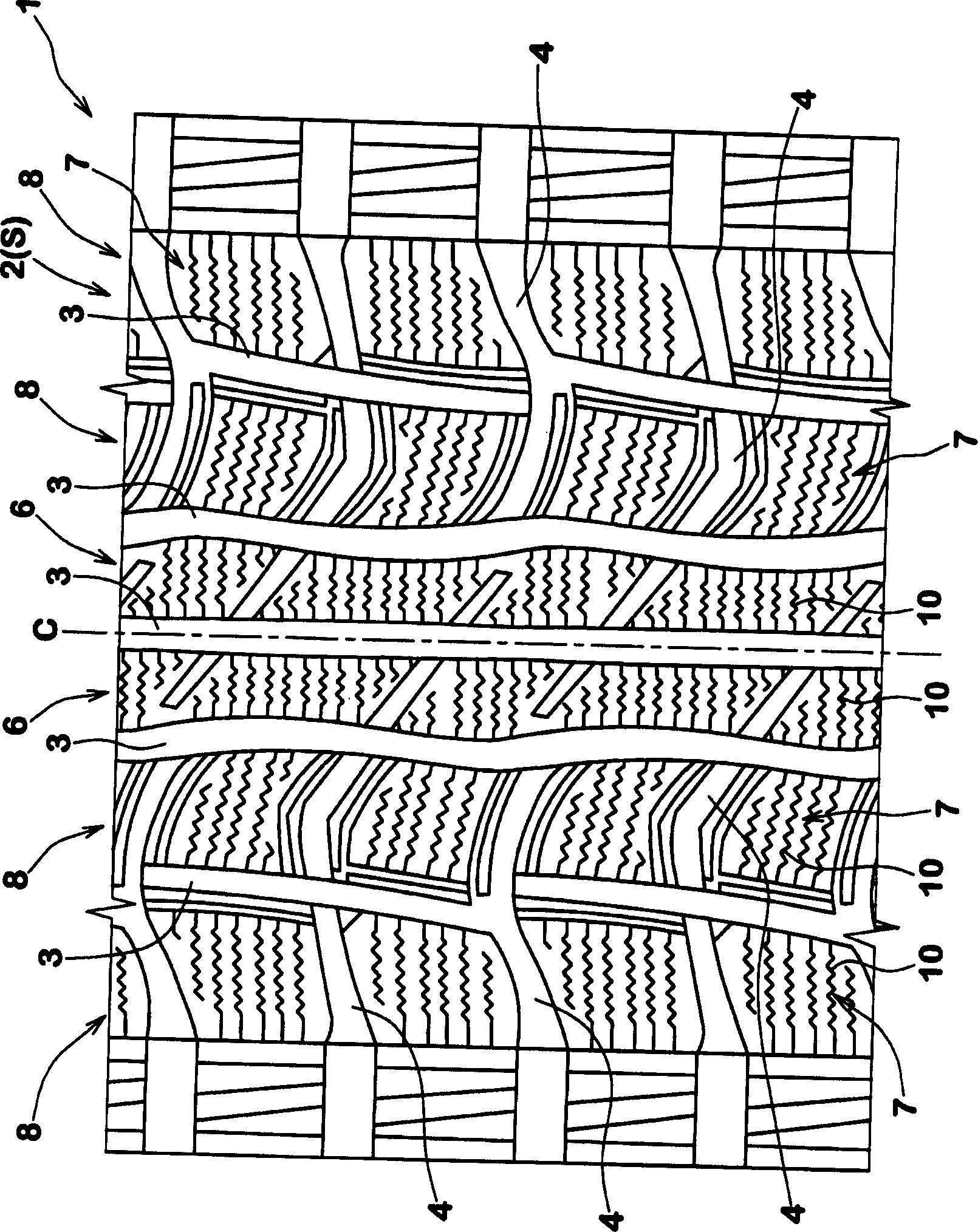
[0023] figure 1 One example of the tread pattern used for this studless tire is shown.

[0024] The tread portion 2 has tread grooves 3 and 4 to divide the tread portion 2 into tread elements 6 and 7 .

[0025] The tread grooves 3 and 4 are used for water drainage, and their width is preferably 3.5 mm or more.

[0026] figure 1 Among them, the tread groove includes a circumferential main groove 3 extending in the tire circumferential direction and a transverse main groove 4 extending in a direction intersecting with the circumferential main groove 3, thereby forming stripes on each side of the tire equator C 6, and two circumferential rows 8 of blocks 7 are formed on the axially outer side of the strip 6. Therefore, in this embodiment, the tread pattern is a so-called rib-block pattern. However, other tread patterns may also be provided, for example a block pattern consisting only of blocks.

[0027] According to the invention, the tread elements, ie strips 6, blocks 7,...


PUM


Abstract

A pneumatic tire comprises a tread portion provided with sipes, the sipes each having a zigzag configuration at any depth from the top of the sipe to a certain depth, and the zigzag configuration having vertexes (Q1) on one side of the zigzag and vertexes (Q2) on the other side of the zigzag, wherein as the depth increases from the top (10a) of the sipe to said certain depth, the vertexes (Q1) onthe one side shift in the longitudinal direction of the sipe and the direction of the shift is turned at least once such that the vertexes (Q1) on the one side first shift towards one direction then towards the other direction, thereby describing a zigzag line (15) extending from the top of the sipe to said certain depth and having at least one tuning point, but the vertexes (Q2) on the other side describe lines (16) which are linear or less zigzag when compared with the zigzag lines (15) described by the vertexes (Q1) on the one side.

Description

technical field [0001] The invention relates to a pneumatic tire, in particular to a sipe structure better suitable for a studless antiskid tire. Background technique [0002] Generally, pneumatic tires are provided with sipes on the tread portion to improve wet grip performance or to reduce the rigidity of tread elements such as blocks, bars, etc. to optimize tread rigidity distribution. Especially in the case of studless tires, a large number of sipes are formed to utilize the edge effect of the sipes when running on icy and snowy roads. However, the rigidity of the tread elements decreases and the deformation of the tread elements increases due to the sipes, so even if the number of sipes is increased, the edge effect does not necessarily increase. As a result, the force holding the edge to the road surface is reduced and the engagement force therebetween, ie the road surface grip, is reduced. [0003] To alleviate deformation of tread elements - such as collapse and ti...

Claims


Application Information

Patent Timeline
Patent Type & Authority Patents(China)
IPC IPC(8): B60C11/12
CPCB60C11/12B60C11/1218B60C2011/1213B29D2030/0613B60C2009/0284Y10S152/902
Inventor 坪野史宽小矢光晴景山尚纪
Owner SUMITOMO RUBBER IND LTD
Learn More