


Quick Research
Generate reliable direction feasibility study reports for your R&D in just a few steps.

Technical Q&A
Discover and master advanced knowledge NOW. Basics, ideas, possibilities, all at once.

Find Solutions
As an expert in R&D theories, this can generate solutions to your technical problems instantly.

Evaluate Feasibility
Analyze your overall solution with one click, know your potential R&D risks in advance.

Monitor Landscape
Get weekly tech updates, stay abreast of the latest tech innovations and key insights.
Resistance analysis method for turbine drill and related computer program product and storage medium
An analysis method and turbo drill technology, applied in the field of machinery, can solve problems such as difficulty in tooth extraction, complex position and shape of teeth to be treated, complex relationship between adjacent anatomical structures, etc., and achieve the effect of reducing extraction resistance and difficulty
- Summary
- Abstract
- Description
- Claims
- Application Information
AI Technical Summary
Problems solved by technology
Method used
Image

Examples
no. 1 example
[0039] Please refer to figure 1 , figure 2 , this embodiment provides a method for using a turbo drill,
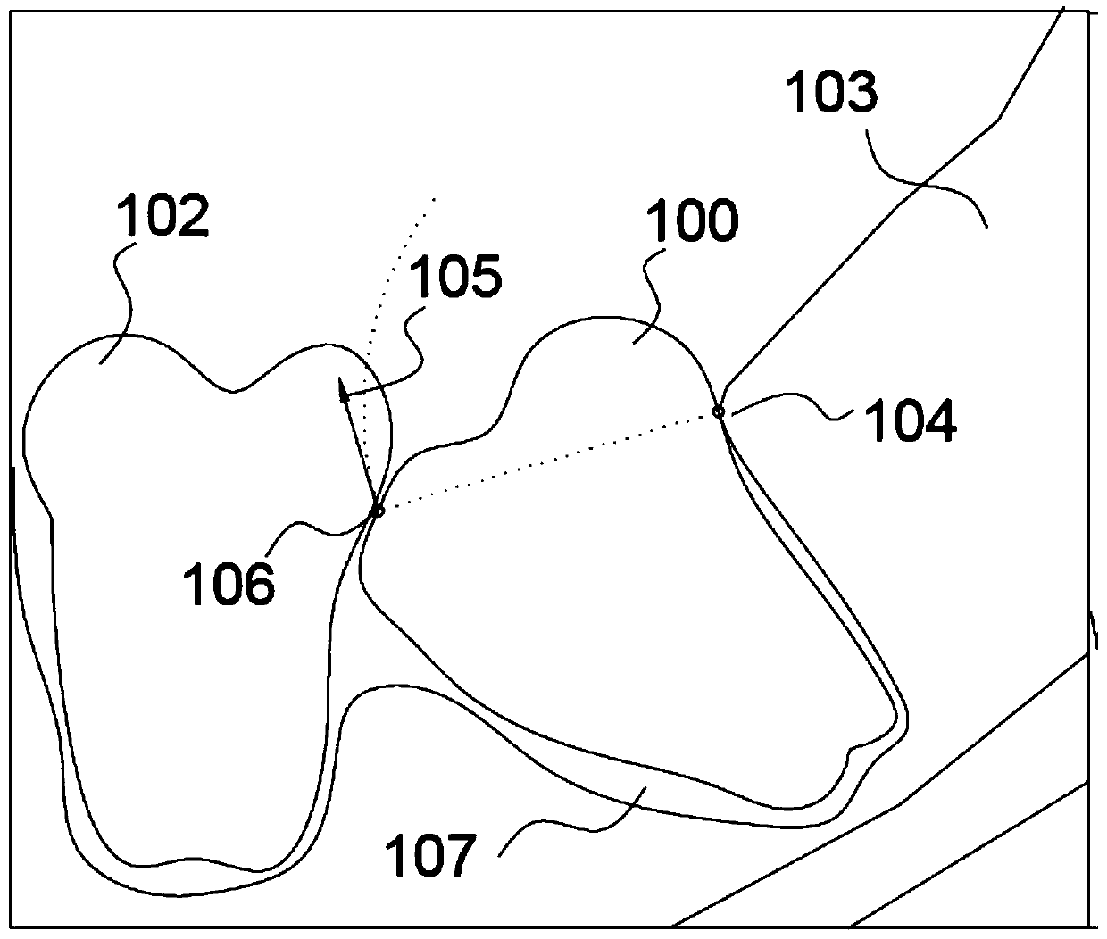
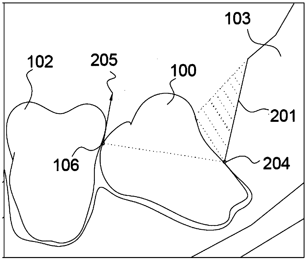
[0040] Such as figure 1 As shown, the tooth 100 to be treated is a tooth that needs to be extracted, the adjacent tooth 102 is a tooth that will hinder the extraction operation with the tooth 100 to be treated, and the alveolar socket 107 is an alveolar socket that wraps the tooth 100 to be treated , the gum 103 is the gum wrapped around the tooth 100 to be treated.
[0041] When extracting the tooth 100 to be treated, in order to cause certain deformation of the alveolar socket 107, during the rotation dislocation process of the tooth 100 to be treated, the position where the tooth 100 to be treated is in contact with the gum 103 is the fulcrum of rotation, We call this fulcrum the first pivot point 104, and the tooth 100 to be treated will use the first pivot point 104 as the fulcrum to pry the tooth 100 to be treated through the action of the tooth extraction tool. ...
no. 2 example
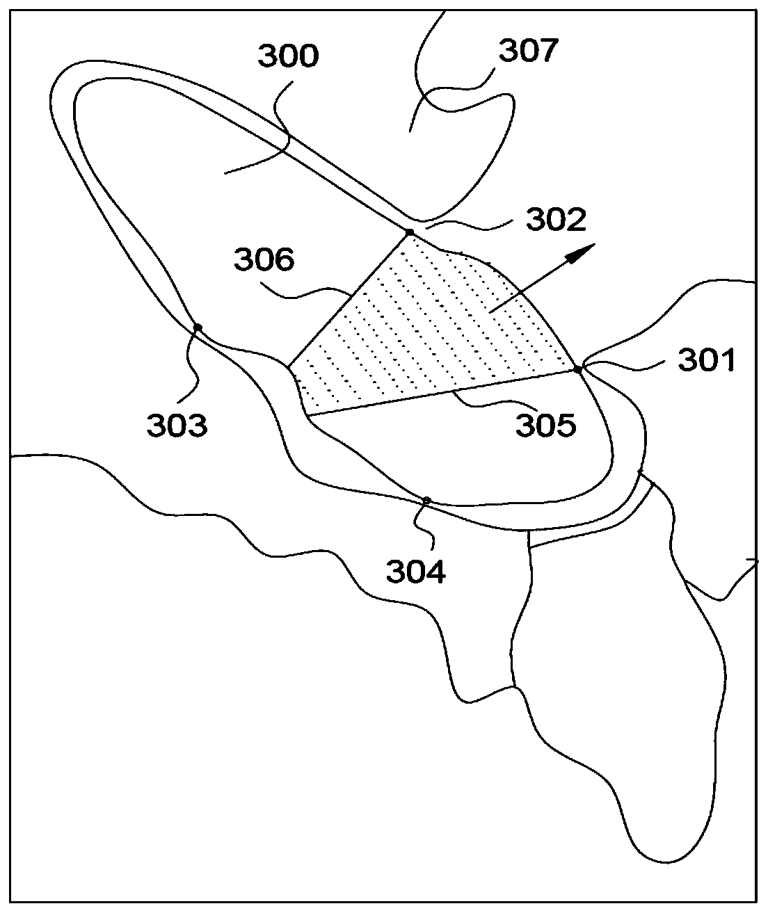
[0049] In this embodiment, the components that are the same as those in the first embodiment are marked with the same reference numerals. Such as image 3 As shown, the laterally growing teeth 300 need to be extracted, and the gingiva 307 is the gingiva that wraps the laterally growing teeth 300, and has the blocking relationship with the laterally growing teeth 300 as described in the previous embodiment. It can be found that if the extraction operation is directly performed on the laterally growing tooth 300, two pivot points as described in the previous embodiment will be generated, such as image 3 Pivot points 301-302 as described in . Multiple resistance points will be generated when the extraction operation is performed with different pivot points as rotation axes, and the resistance points corresponding to the pivot points 301-302 are 303-304. As shown in the figure, the cutting lines 305-306 are determined on the laterally growing teeth 300, so that the shape of the...
no. 3 example
[0051] In this embodiment, the components that are the same as those in the first embodiment are marked with the same reference numerals. As mentioned in the previous embodiment, when the relationship between the tooth to be extracted and the adjacent teeth or gums is more complicated, it is necessary to set the cutting line multiple times. It can be imagined that after each cutting action, a new pivot point will be generated. That is, the second pivot point described in the previous embodiment. It should be noted that the serial number of the pivot point increases with the number of cuts. For ease of understanding and better visualization, this specification uses the second pivot point instead of the generated sequence pivot point to describe specific steps.
PUM
 Abstract
Description
Claims
Application Information
 - R&D Engineer
- R&D Manager
- IP Professional
- Industry Leading Data Capabilities
- Powerful AI technology
- Patent DNA Extraction
Browse by: Latest US Patents, China's latest patents, Technical Efficacy Thesaurus, Application Domain, Technology Topic, Popular Technical Reports.
© 2024 PatSnap. All rights reserved.Legal|Privacy policy|Modern Slavery Act Transparency Statement|Sitemap|About US| Contact US: help@patsnap.com