Method for detecting load current by using signal in work cycle of pulsewidth modulation controller

A load current, pulse width modulation technology, applied in the direction of measuring current/voltage, detecting faulty computer hardware, measuring electrical variables, etc., can solve problems such as power consumption, wasted system, and fan speed cannot be real-time.

Inactive Publication Date: 2006-07-05
AOPEN
View PDF0 Cites 14 Cited by
  • Summary
  • Abstract
  • Description
  • Claims
  • Application Information

AI Technical Summary

Problems solved by technology

However, this method has the following disadvantages: 1. The accuracy of current detection will be affected by the error of the resistance component itself, the external environment (such as temperature, etc.) or other uncertain factors; 2. When the current is large, the resistance Components cause additional power consumption, which will eventually be wasted in the system as heat
However, the above-mentioned control mode about the fan has the following disadvantages: 1. The temperature of the CPU responds only after the load current changes, and the fan is controlled after the temperature change of the CPU is detected by a relevant thermal device (such as a thermistor). , there will be a delay time, so that the speed of the fan cannot respond in real time to the change of the load current
2. This fan control system is a one-stage control mode, which cannot be more efficiently switched and adjusted according to the high and low temperature changes of the load
[0005] In view of the above, it is urgent to propose a method for detecting the load current using the duty cycle signal of the PWM controller, which can detect the current change of the load current in real time and quickly, and it is mainly implemented by hardware, so it can avoid Problems caused by unstable software operation or downtime

Method used


Image

  • Method for detecting load current by using signal in work cycle of pulsewidth modulation controller
  • Method for detecting load current by using signal in work cycle of pulsewidth modulation controller
  • Method for detecting load current by using signal in work cycle of pulsewidth modulation controller

Examples


Embodiment Construction

[0047] Embodiments of the present invention will be described in detail below in conjunction with the accompanying drawings. It is particularly noted here that all illustrations are in simple form and not drawn to scale, and the dimensions are exaggerated to facilitate understanding of the present invention.

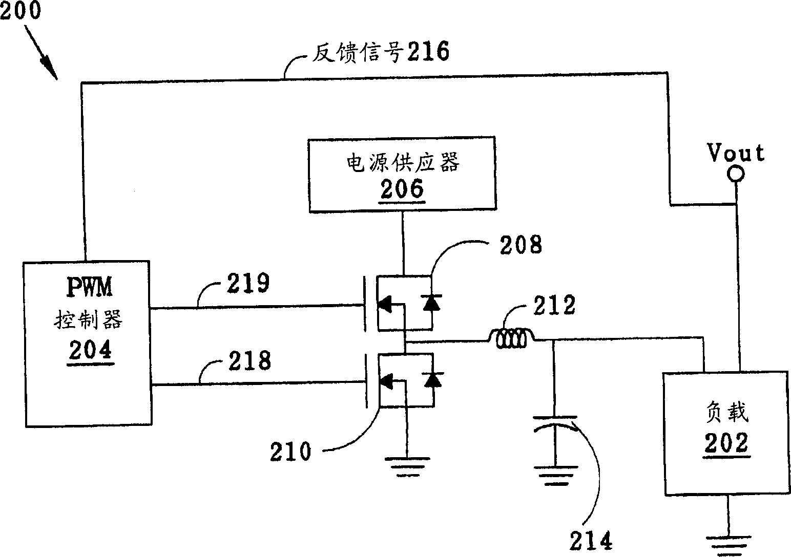
[0048] As shown in Figure 2, it is a schematic diagram of a pulse width modulation switching regulator (PWM switching regulator) circuit 200 according to a basic electronic circuit of the present invention, which includes: load 202 (or electronic components, such as control chips, servers and CPUs, etc. ), a pulse width modulation controller (PWMcontroller) 204, a power supply (power supply) 206, a high side metal oxide semiconductor (high side MOS) 208, a low side metal oxide semiconductor (low side MOS) 210 and an inductor 212 A filter circuit composed of a capacitor 214 and other components, wherein the PWM controller 204 receives a feedback signal 216 from the output...


PUM


Abstract

The invention discloses a method for detecting a load current by the duty cycle signal of a PWM controller, comprising: providing a PWM controller to stabilize the voltage of a load; installing a PWM duty cycle sensor, where the sensor receives a duty cycle signal from the PWM controller to detect the load current; and using the detection result to dynamically regulate and control working frequency and working voltage of the road and the related radiator. The invention can real-timely detect load current variation and reduce unnecessary power consumption on the load.

Description

technical field [0001] The invention relates to a method for detecting load current, in particular to a method for detecting the load current by utilizing the duty cycle pulse waveform signal of a pulse width modulation controller. Background technique [0002] Current detection technology plays a very important role in electronic circuits, especially the part of the power circuit, because the power circuit is like the heart of the body, it must continuously supply blood to every corner of the body, just like high blood pressure is generally harmful to health Therefore, how to detect the current accurately and in real time will have a great impact on the stability and safety of the entire electronic circuit system. At present, the existing current detection method mainly uses resistance conversion technology: a low-value resistor is connected in series on the power supply path. When the current flows through this resistor, a slight voltage drop will occur. Using Ohm's law, ...

Claims


Application Information

Patent Timeline
Patent Type & Authority Applications(China)
IPC IPC(8): G01R19/00G01R19/12G06F11/22
Inventor 邱志凯陈剑辉
Owner AOPEN
Why Eureka
Try Eureka