
Actuator control system

A control system and actuator technology, applied in the control system, motor generator control, current controller, etc., can solve the problems of deterioration of durability and high production cost of electric actuators

Active Publication Date: 2006-07-05
SMC CORP
View PDF2 Cites 12 Cited by
  • Summary
  • Abstract
  • Description
  • Claims
  • Application Information

AI Technical Summary

Problems solved by technology

[0008] However, when the electric actuator according to the conventional technology disclosed in the above-mentioned Japanese Laid-Open Patent Publication No. 11-30234 is performed according to the forward and backward movement performed by the piston rod similar to a hydraulic cylinder without using any complicated control device or the like When motion is applied, for example, to a pressing operation of a workpiece at any intermediate position between one stroke and another stroke, the durability of the electric actuator is deteriorated because of vibration or shock caused when abutting the workpiece is delivered via a slider to a screw shaft or similar
[0009] In addition, when the technical concept disclosed in Japanese Laid-Open Patent Publication No. 2002-66969 is applied, for example, to an electric actuator for converting a rotary motion of a motor into a linear motion of a slider or the like, it is necessary to provide such as code Detectors such as detectors and resolvers, as well as control circuits in order to control, for example, the position and speed of movement of a slider, become expensive to produce

Method used


Image

  • Actuator control system
  • Actuator control system
  • Actuator control system

Examples


Embodiment Construction

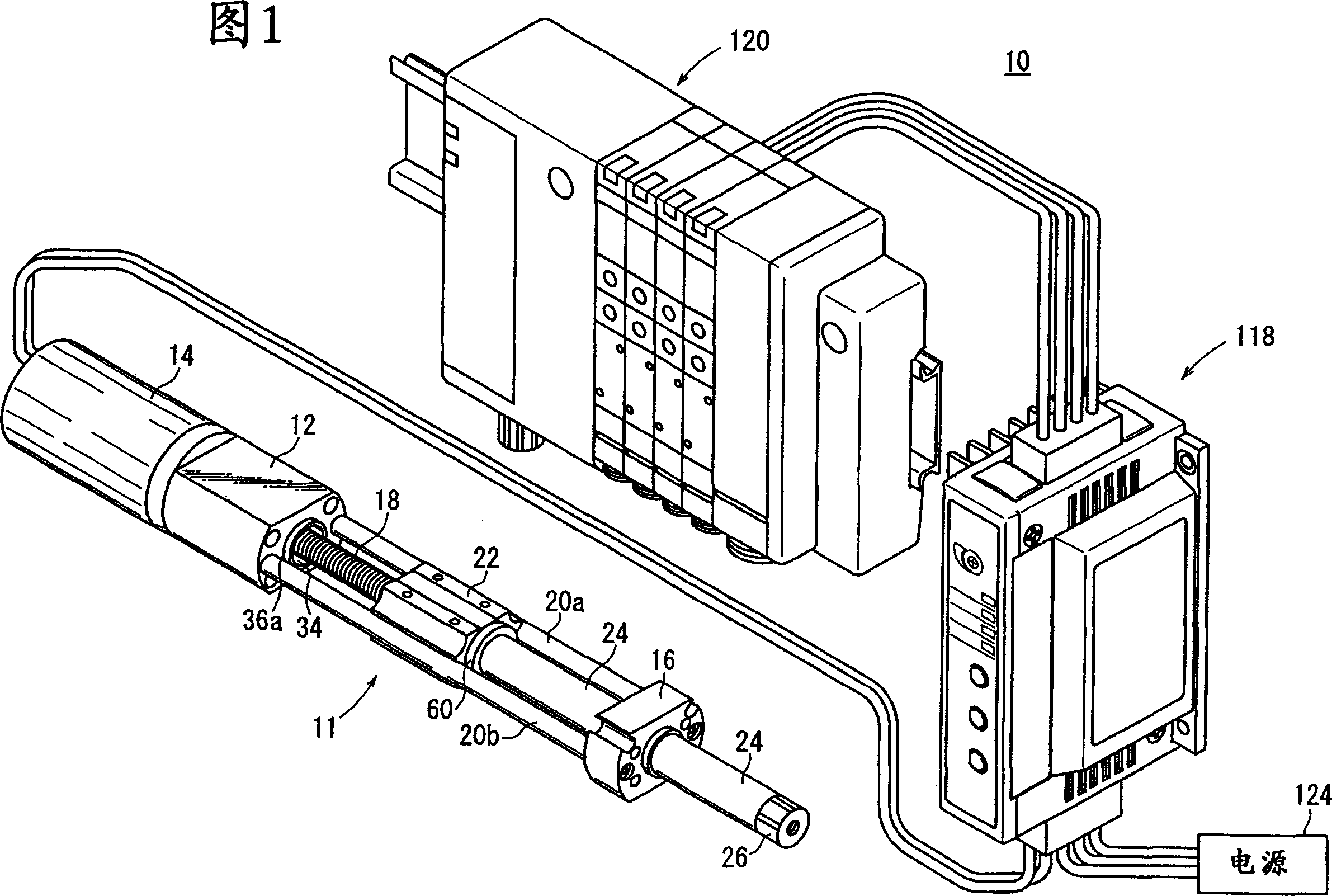
[0077] Referring to FIG. 1, numeral 10 denotes an actuator control system according to an embodiment of the present invention.

[0078] The actuator control system 10 includes an electric actuator 11, wherein the piston 22 and the piston rod 24 perform linear reciprocating motion under the driving action of the rotary drive source 14; The rotary drive source 14; the controller 120, which exports the direction indicating signal to the driver 118; and the power supply 124, which is connected to the driver 118 via a connector.

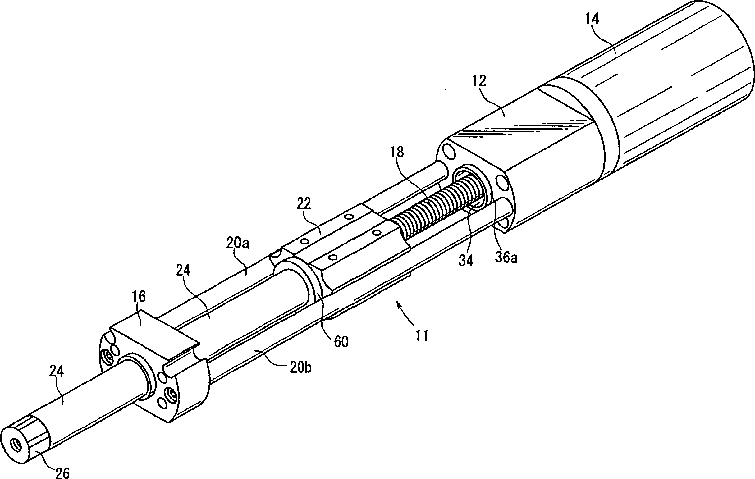
[0079] Such as figure 2 As shown, the electric actuator 11 includes a housing 12, which is composed of a substantially flat block member; a rotary drive source 14, which is connected to one end of the housing 12; a rod housing (end block) 16, which is arranged in relation to the housing. 12 at a predetermined distance, and on the side opposite to the side to which the rotary drive source 14 is connected; and a feed screw shaft (driving force transmission...


PUM


Abstract

An actuator control system comprises an electric actuator, a driver, and a controller. The electric actuator is provided with a buffering mechanism which absorbs impact applied to a piston rod. The buffering mechanism includes piston dampers which absorb impact applied to a piston, a first end damper which is provided at an end of a housing facing the piston, and a second end damper which is provided on a rod cover separated from the housing by a predetermined distance.

Description

technical field [0001] The present invention relates to an actuator control system comprising, for example, an electric actuator allowing a linear reciprocating movement of a displacement member under the rotary drive of a rotary drive source, and protecting the rotary drive for driving the electric actuator source control unit. Background technique [0002] Transfer devices such as actuators have hitherto been used, for example, to transfer workpieces. [0003] An electric actuator related to conventional technology is shown in FIGS. 63 and 64 (see, for example, Japanese Laid-Open Patent Publication No. 11-30234). [0004] An electric actuator 1 relating to conventional technology has a slider 4 displaceable along a groove 3 of a frame 2 and a screw shaft 6 driven by an electric motor not shown and screwed onto a nut member 5, The nut member 5 is detachable with respect to the slider 4 . Screw shaft support members 7a, 7b that rotatably support the screw shaft 6 are prov...

Claims


Application Information

Patent Timeline
IPC IPC(8): F16F15/04F16H25/20H02H7/085H02P6/08H02P7/06H02P8/12H02P6/28
Inventor 永井茂和齐藤昭男杉山亨增井隆一广瀬毅宫原正树
Owner SMC CORP
Learn More