Production plant of outside loop for slurry of polyethylene

A technology of production equipment and external circulation, which is applied in the field of polyethylene slurry external circulation production equipment, can solve the problems of large investment costs and achieve the effects of low investment costs, increased floor space, and increased heat exchange area

Inactive Publication Date: 2006-07-05
SHANGHAI BOLONG EQUIP TECH CO LTD
View PDF0 Cites 10 Cited by
  • Summary
  • Abstract
  • Description
  • Claims
  • Application Information

AI Technical Summary

Problems solved by technology

The investment cost of this kind of transformation is relatively large, and the equipment layout of many existing devices has been determined, so there is no space to add new production lines and equipment

Method used


Image

  • Production plant of outside loop for slurry of polyethylene

Examples


Embodiment Construction

[0014] The structure of the polyethylene slurry external circulation production device of the present invention will be further described below in conjunction with the accompanying drawings.

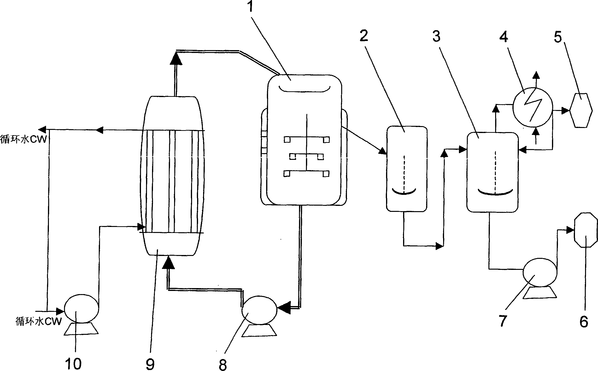
[0015] like figure 1 As shown, the polyethylene slurry external circulation production device of the present invention comprises: a polymerization reactor 1, a dilution tank 2 connected to the output of the polymerization reactor 1, a flash tank 3 connected to the bottom of the dilution tank, and a flash tank The flash tank condenser 4 connected to the tank 3 and the slurry delivery pump 7, the tail gas compressor 5 connected to the gas output end of the flash tank condenser 4, the centrifugal pump 6 connected to the output end of the slurry delivery pump 7, and the polymerization reactor 1 A slurry cooling pump 8 connected to the bottom, the bottom is connected to the output of the slurry cooling pump 8, the output of the top is connected to the slurry cooler 9 input from the top of the...


PUM


Abstract

A slurry outside circulation facility for polyethylene manufacture is disclosed here. The scheme adopted is that slurry inside the polymerization reactor is extracted from the bottom, pumped into a slurry cooler and then transmitted back into the polymerization reactor. The heat of slurry is removed by circular cooling outside the polymerization reactor, which increases the heat-exchange area and helps remove a part of the reaction heat generated during polymerization. By increasing the mass of polymerized polyethylene, the production capacity of original facilities can be promoted by over 50%. Compared to former technological alteration, the slurry outside circulation facility for polyethylene manufacture has the advantages of low investment cost, same area, low alteration period and convenient implementation.

Description

technical field [0001] The invention relates to a polyethylene production device, in particular to a polyethylene slurry external circulation production device. Background technique [0002] The equipment for producing polyethylene by slurry method includes a polymerization reactor, a dilution tank connected to the output of the polymerization reactor, a flash tank connected to the bottom of the dilution tank, a flash tank condenser connected to the flash tank and slurry Pump. In the prior art, after the device is put into production, its production capacity is basically determined. If it is necessary to increase the output, it is necessary to increase the production line, that is, add a new parallel polymerization reactor. The investment cost of this kind of transformation is relatively large, and the equipment layout of many existing devices has been determined, so there is no space to add new production lines and equipment. Contents of the invention [0003] In order...

Claims


Application Information

Patent Timeline
Patent Type & Authority Applications(China)
IPC IPC(8): C08F2/01C08F110/02
Inventor 张玲珑
Owner SHANGHAI BOLONG EQUIP TECH CO LTD
Why Eureka
Try Eureka