Method and equipment for oil-water separation
A technology for oil-water separation and fluid separation, applied in separation methods, liquid separation, general water supply saving, etc., can solve problems such as inapplicability of oil and seawater
Inactive Publication Date: 2006-07-05
INST OF ELECTRICAL ENG CHINESE ACAD OF SCI +1
View PDF1 Cites 14 Cited by
- Summary
- Abstract
- Description
- Claims
- Application Information
AI Technical Summary
Problems solved by technology
This method does not need to put additional substances into the oily seawater, but it is mainly suitable for the oil-water separation and recovery of floating oil on the sea surface, and is not suitable for mixing oil and seawater. The oil is mixed in seawater in the form of oil beads, or even emulsified. Oily seawater, such as the oil-water separation of a large amount of oily tank water
Method used
View moreImage
Smart ImageViewing Examples
Examples
Embodiment 1
Embodiment 2
Login to View More PUM
 Abstract
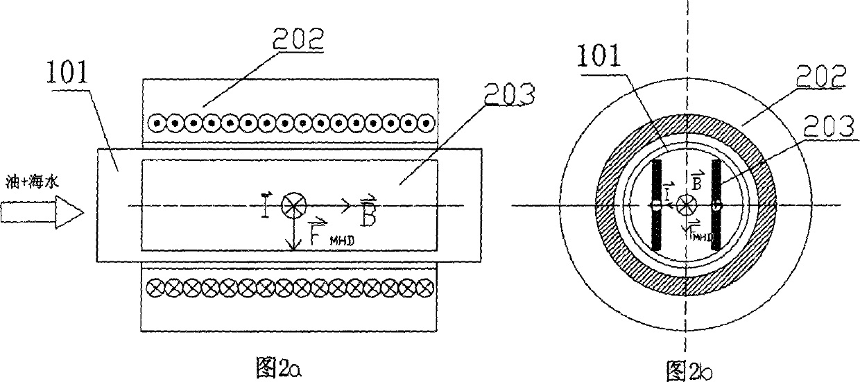
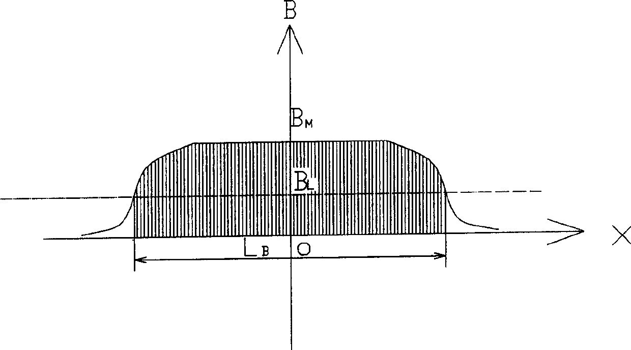
This is a new method and equipment for oil-water separation. This invention is based on the fundamental principle that the magnetic force which the electrified seawater suffers from the perpendicular magnetic field is FMHD=Ií‡B. According to this principle, each of the electrified seawater micelles in the oil-seawater mixture is extruded downwards as a result of the downward magnetic force after they enter into the interaction region between the electric and magnetic fields in the electromagnetic fluid separation passage. The buoyancy of the oil droplet in the seawater is of the same magnitude but in opposite directions, so the oil droplets float upward and assemble in the upper layer of the seawater. Consequently the oil and water are separated into two layers and depart from each other at the vent of the separation passage. There are two constitutional modes for the equipment that applies this invention: (1) solenoid superconductive magnet, tubular electromagnetic fluid separation passage and built-in passage tube parallel electrode pair; (2) saddle-polar superconductive magnet, tubular electromagnetic fluid separation passage and built-in passage tube annular electrode pair. Under the effect of magnetic force in the designed working condition of this invention, the rising velocity of oil-water separation can be accelerated by 1~2 order-of-magnitude in contrast to the result of the specific gravity difference between oil and water.
Description
technical field The present invention relates to an oil-water separation method and device for oily seawater, in particular to an oil-water separation method and device utilizing electromagnetic fluid power. Background technique The operation of seagoing ships and marine oil spill accidents produce a large amount of oily cabin water and oily seawater, which may cause serious pollution to the environment. Regardless of the needs of environmental protection and energy saving, it is expected to separate and recycle oil and water quickly and efficiently. One of the existing oil-water separation methods is the magnetic separation method, which spreads lipophilic porous magnetic material particles into the oily seawater, absorbs the oily dirt mixed in the seawater, and then collects the magnetic material particles to separate the oily dirt from the seawater; the second method It spreads the oil dispersant to the oil slick on the sea surface. Due to the function of the oil disper...
Claims
Login to View More Application Information
Patent Timeline
 IPC IPC(8): C02F1/40C02F1/48E02B15/04
CPCY02A20/204
Inventor 沙次文彭燕杨天夫杨天力郑毅赵凌志李然张国艳
Owner INST OF ELECTRICAL ENG CHINESE ACAD OF SCI
Features
- R&D
- Intellectual Property
- Life Sciences
- Materials
- Tech Scout
- Unparalleled Data Quality
- Higher Quality Content
- 60% Fewer Hallucinations
Learn More Browse by: Latest US Patents, China's latest patents, Technical Efficacy Thesaurus, Application Domain, Technology Topic, Popular Technical Reports.
© 2025 PatSnap. All rights reserved.Legal|Privacy policy|Modern Slavery Act Transparency Statement|Sitemap|About US| Contact US: help@patsnap.com


