Three measuring range potential difference meter using conversion branch having four measuring discs

A potentiometer and measuring disc technology, which is applied in the direction of AC/DC potential difference measurement devices, etc., can solve the problems of increasing the size of the instrument and the resolution of the potentiometer being as small as 0.1μv.

Inactive Publication Date: 2006-06-28
骆乃光
View PDF0 Cites 11 Cited by
  • Summary
  • Abstract
  • Description
  • Claims
  • Application Information

AI Technical Summary

Problems solved by technology

[0002] For the currently produced potentiometer, when there are more than three measuring discs, there will be switch contact resistance and variation between the two measuring terminals. Therefore, even if the working current is as small as 0.1mA, the brushes and contacts of the switch are not only made of silver copper. Composite materials, the contact area is also made q

Method used


Image

  • Three measuring range potential difference meter using conversion branch having four measuring discs

Examples


Embodiment Construction

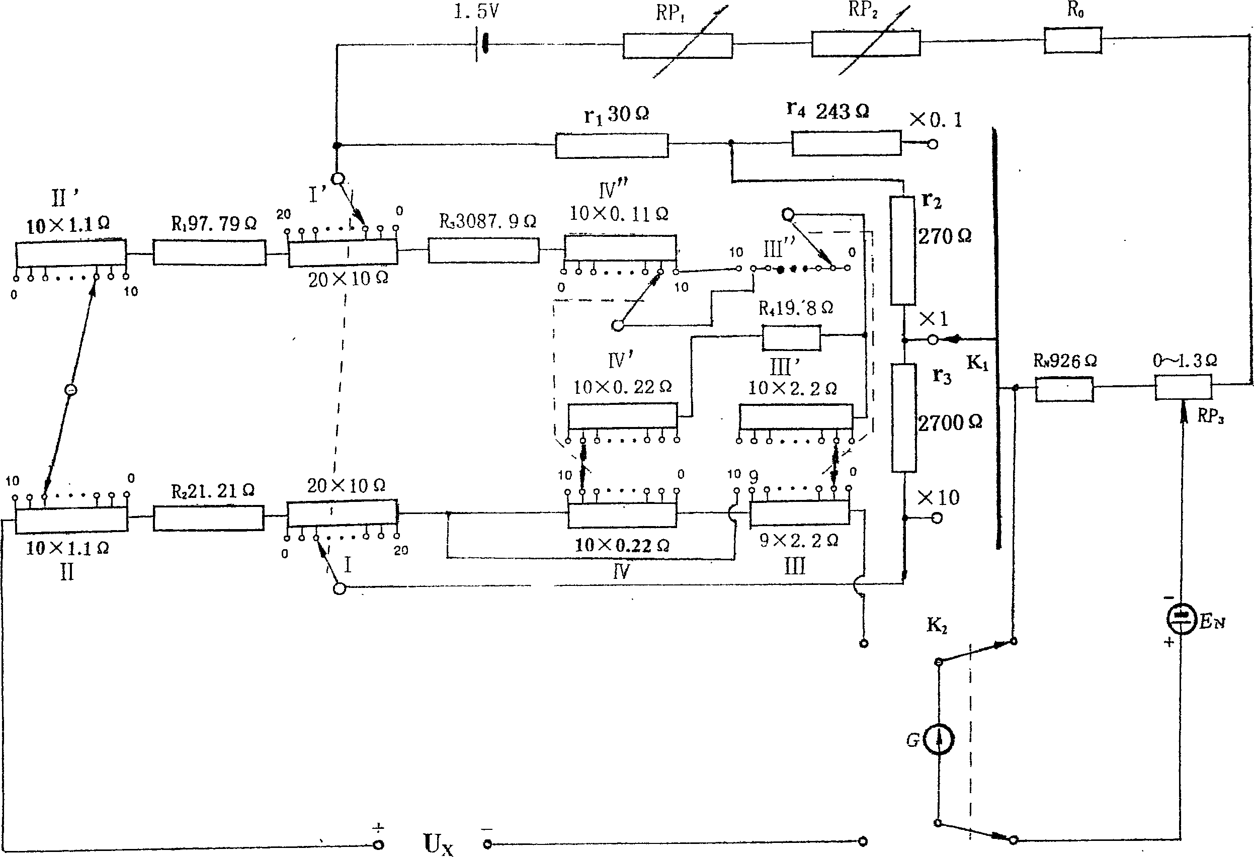
[0007] by "U x "The positive electrode passes through each measuring disc, and then passes through the switch K 2 to "U x "The negative pole is the measurement circuit, from the positive pole of the power supply through the measurement step switch to the setting resistance RN and RP 3 , then to resistor R 0 , adjustable resistor RP 2 and RP 1 Finally, back to the negative pole of the power supply is the working circuit, from the positive pole of the standard battery EN through the switch K 2 , to the setting resistor RN and RP 3 , and then to the negative pole of the standard battery is the standard circuit. When all four discs throw "0", the left resistance between the two brushes of the first step disc is 330Ω, the right resistance is equal to 3300Ω, and the total resistance between the two brushes of the first step disc is 300Ω, so the first disc 10 / 11 of the total current between the two brushes flows on the left and 1 / 11 on the right. When throwing the 10th point ...


PUM


Abstract

A three¿C range potential difference meter with four measuring discs and applying conversion branch is composed of four measuring discs as 20x 10 omega, 10x 1.1 omega, 9x 2.2 omega and 10x 0.22 omega. It is featured as connecting all measuring resistances directly by conducting wire to exclude contact resistance and variation of measuring ¿C stepping switch out of measuring result, using integer power of one digit number or two digit number multiplying by ten as value of resistance used on range switch ¿C over.

Description

technical field [0001] The invention relates to an instrument for measuring DC voltage. Background technique [0002] For the currently produced potentiometer, when there are more than three measuring discs, there will be switch contact resistance and variation between the two measuring terminals. Therefore, even if the working current is as small as 0.1mA, the brushes and contacts of the switch are not only made of silver copper. Composite materials, the contact area is also made quite large to reduce the impact of the variation of the measurement switch when switching step by step, which makes the volume of the instrument larger. Even so, the resolution of the potentiometer cannot be made as small as 0.1μv. In addition, there is also the influence of the thermoelectric potential of the switch and the variable thermoelectric potential of the contact. Contents of the invention [0003] The problem to be solved by the present invention is that when there are four step disc...

Claims


Application Information

Patent Timeline
IPC IPC(8): G01R17/20
Inventor 骆乃光
Owner 骆乃光
Why Eureka
Try Eureka