Device angle for regulating of vehicle light

A technology for angle adjustment devices and car lights, which is applied to lighting devices, transmission devices, friction transmission devices, etc., and can solve problems such as space occupation, low adjustment, and increased volume of adjustment devices.

Inactive Publication Date: 2006-06-28
黄湘益
View PDF0 Cites 2 Cited by
  • Summary
  • Abstract
  • Description
  • Claims
  • Application Information

AI Technical Summary

Problems solved by technology

[0002] Generally, the angle of the headlights installed on vehicles is fixed, and the angle of illumination cannot be adjusted depending on the type of vehicle, which may cause the lighting angle to be too high or too low. Therefore, an angle adjustment device is installed on the headlights. General headlight angle adjustment device, as shown in Figure 1, figure 2 As shown, there is mainly a screw rod 11 connected with the car lamp body, the screw rod 11 is screwed with the screw hole 121 of a bushing 12, and one end of the bushing 12 extends a polygonal bump 122, and the bump 122 is It is clamped with the locking hole 131 of a gear plate 13, and an adjustment rod 14 intersecting with the screw rod 11 at 90 degrees is provided. The end of the adjustment rod 14 is clamped with a gear 15, and the gear 15 is meshed with the gear plate 13. These components are located in a fixed seat 16 and a positioning seat 17, and its screw rod 11 and adjusting rod 14 protrude from the fixing seat 16 and the positioning seat 17. When the adjusting rod 14 is rotated, the gear 15, the gear plate 13 and The linkage of the bushing 12 drives the displacement of the screw rod 11 to adjust the angle of the lamp. However, in the conventional lamp angle adjustment device, a transmission mechanism must be installed outside the adjustment rod 14 to drive the adjustment rod 14 to rotate. , so it is necessary to occupy another installation space of a transmission mechanism, and there is no restriction mechanism for the displacement of the screw rod 11 in the general adjustment device, often because the displacement stroke of the screw rod 11 cannot be accurately set, and the screw rod 11 is overextended or retracted excessively , so it is necessary to additionally install a limit mechanism for the screw, which will increase the size of the overall adjustment device and take up a lot of space

Method used


Image

  • Device angle for regulating of vehicle light
  • Device angle for regulating of vehicle light
  • Device angle for regulating of vehicle light

Examples


Embodiment Construction

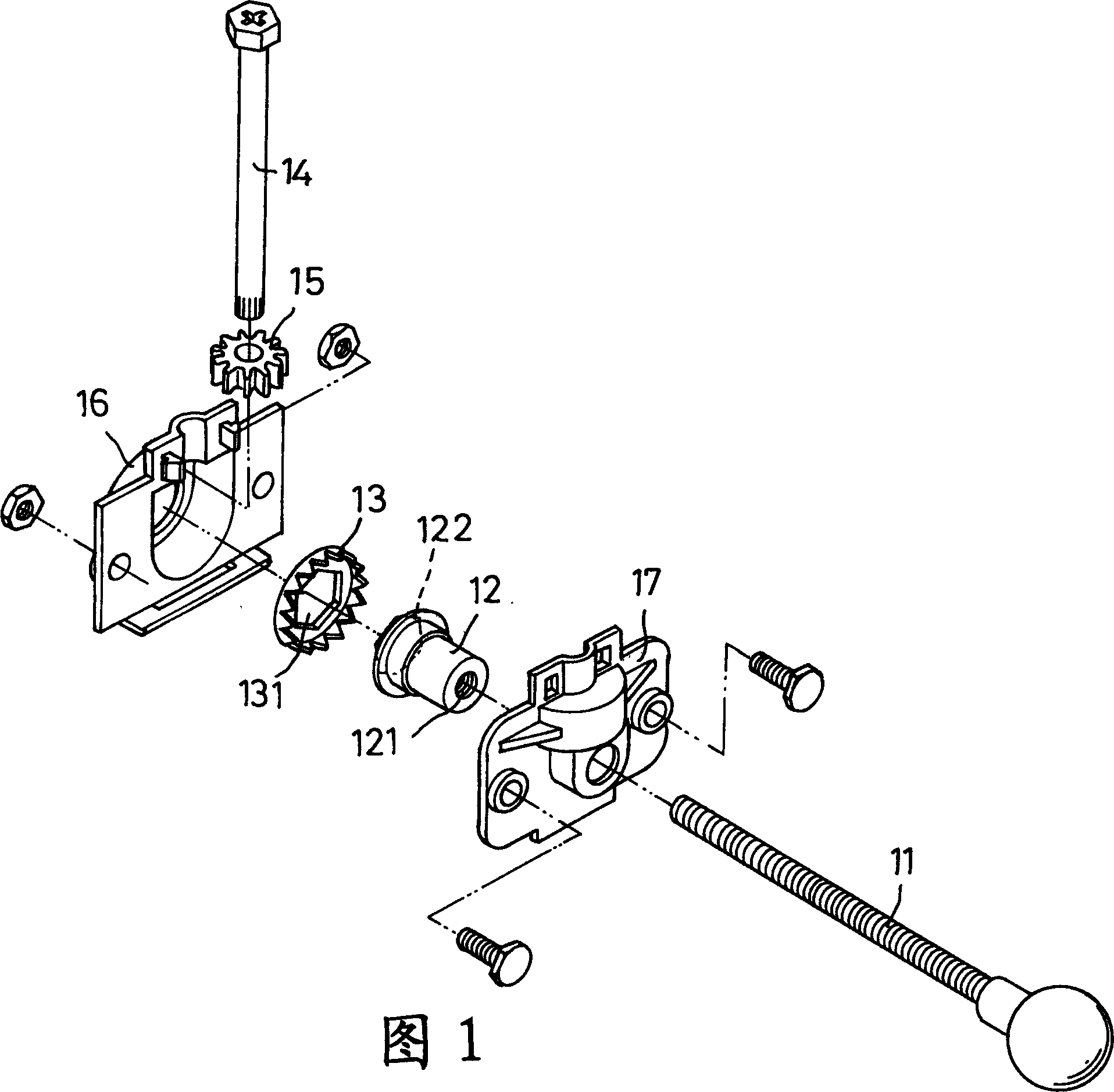
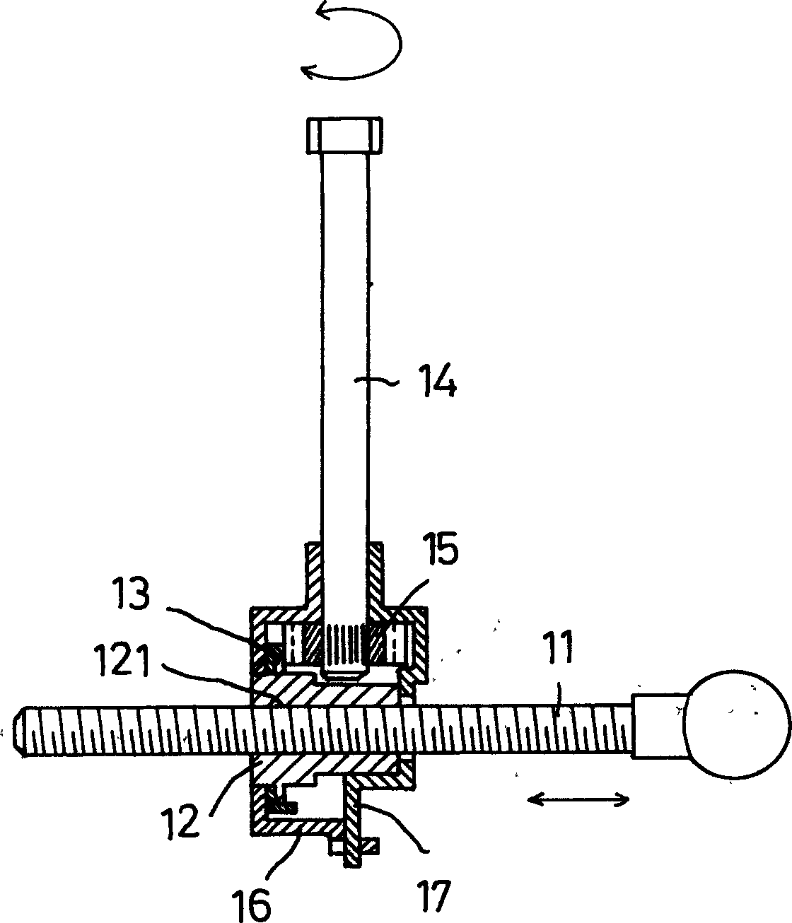
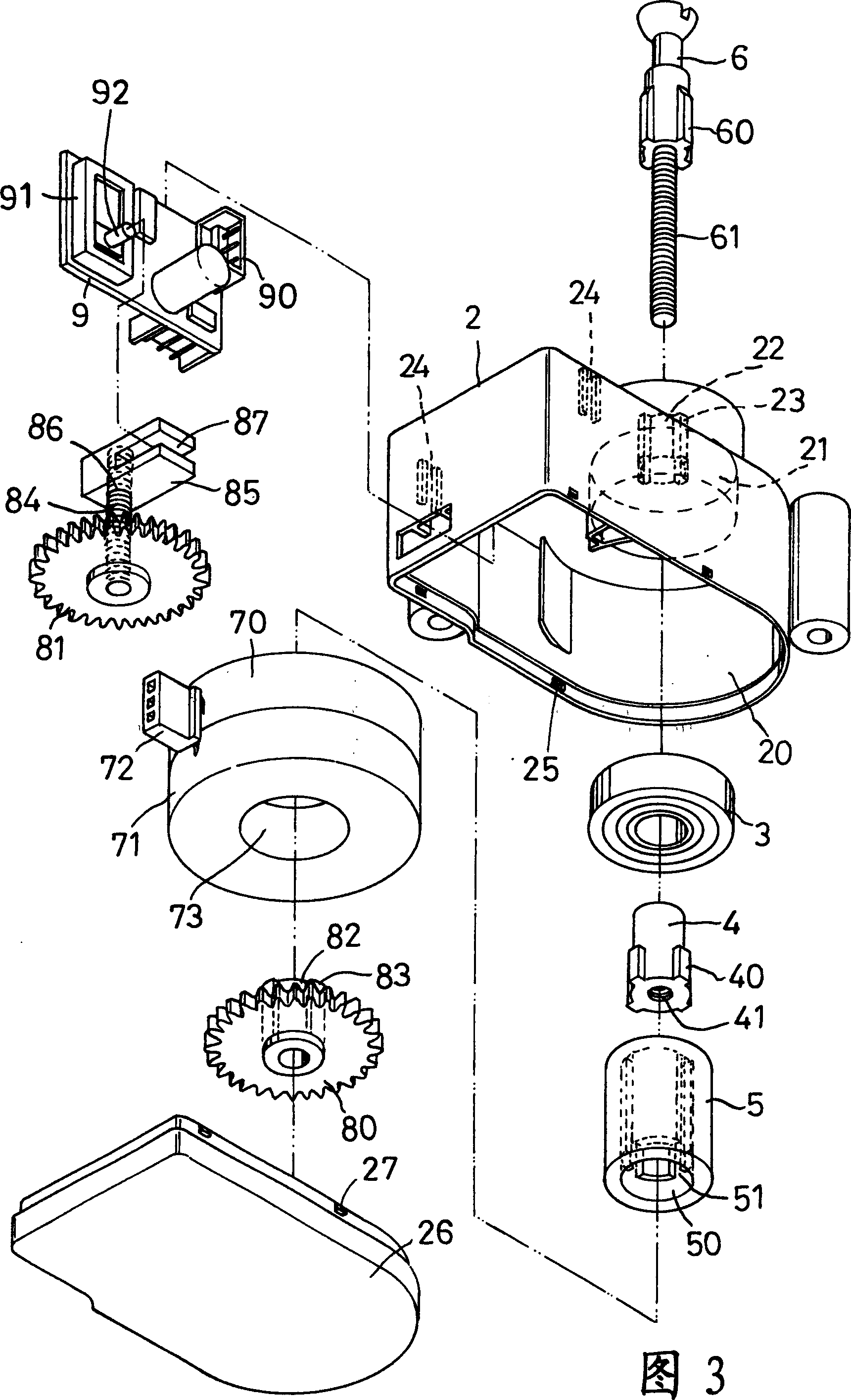
[0015] First of all, please refer to Fig. 3, the present invention is mainly provided with a casing 2, the casing 2 is provided with a chamber 20, the chamber 20 is provided with an alcove 21, and the alcove 21 is provided with a perforation 22 , the peripheral wall of the perforation 22 is provided with several positioning slots 23, the inner wall of the chamber 20 is oppositely provided with two slots 24, the wall surface of the casing 2 is provided with several embedded holes 25, and the bottom of the casing 2 is covered. There is a bottom cover 26, and several inlays 27 are arranged on the wall surface of the bottom cover 26; a bearing 3 is arranged in the alcove 21 of the casing 2; a connecting piece 4 is arranged under the bearing 3, and the connecting piece 4 One end of the connecting piece is set on the bearing 3, the peripheral wall of the connecting piece 4 is provided with several convex bodies 40, and the center of the connecting piece 4 is provided with a screw hol...


PUM


Abstract

The invention is a car light angle regulating device, composed mainly of casing, bearing, connector, magnet, push rod, forward rotating coil, reversing coil, drive gear, driven gear and circuit board, using the circuit board in the casing to control to electrify the forward rotating coil or reversing coil to make the magnet rotate forward or reversely and rotate the connection piece and drive gear to make the push rod move up or down and simultaneously making a driving block on the driven gear move synchronously to drive the salient rod of a limiting switch on the circuit board to control the push rod at the upper or lower limit so as to turn off the limiting switch to prevent the push rod from excessively extending outward or inward and making the driving more reliable; and the whole bulk is small.

Description

technical field [0001] The invention relates to a vehicle lamp angle adjustment device. Background technique [0002] Generally, the angle of the headlights installed on vehicles is fixed, and the angle of illumination cannot be adjusted depending on the type of vehicle, which may cause the lighting angle to be too high or too low. Therefore, an angle adjustment device is installed on the headlights. General headlight angle adjustment device, as shown in Figure 1, figure 2 As shown, there is mainly a screw rod 11 connected with the car lamp body, the screw rod 11 is screwed with the screw hole 121 of a bushing 12, and one end of the bushing 12 extends a polygonal bump 122, and the bump 122 is It is clamped with the locking hole 131 of a gear plate 13, and an adjustment rod 14 intersecting with the screw rod 11 at 90 degrees is provided. The end of the adjustment rod 14 is clamped with a gear 15, and the gear 15 is meshed with the gear plate 13. These components are located...

Claims


Application Information

Patent Timeline
IPC IPC(8): F21V14/00F16H19/02
Inventor 黄湘益
Owner 黄湘益
Why Eureka
Try Eureka