Document transported typed scanning mechanism

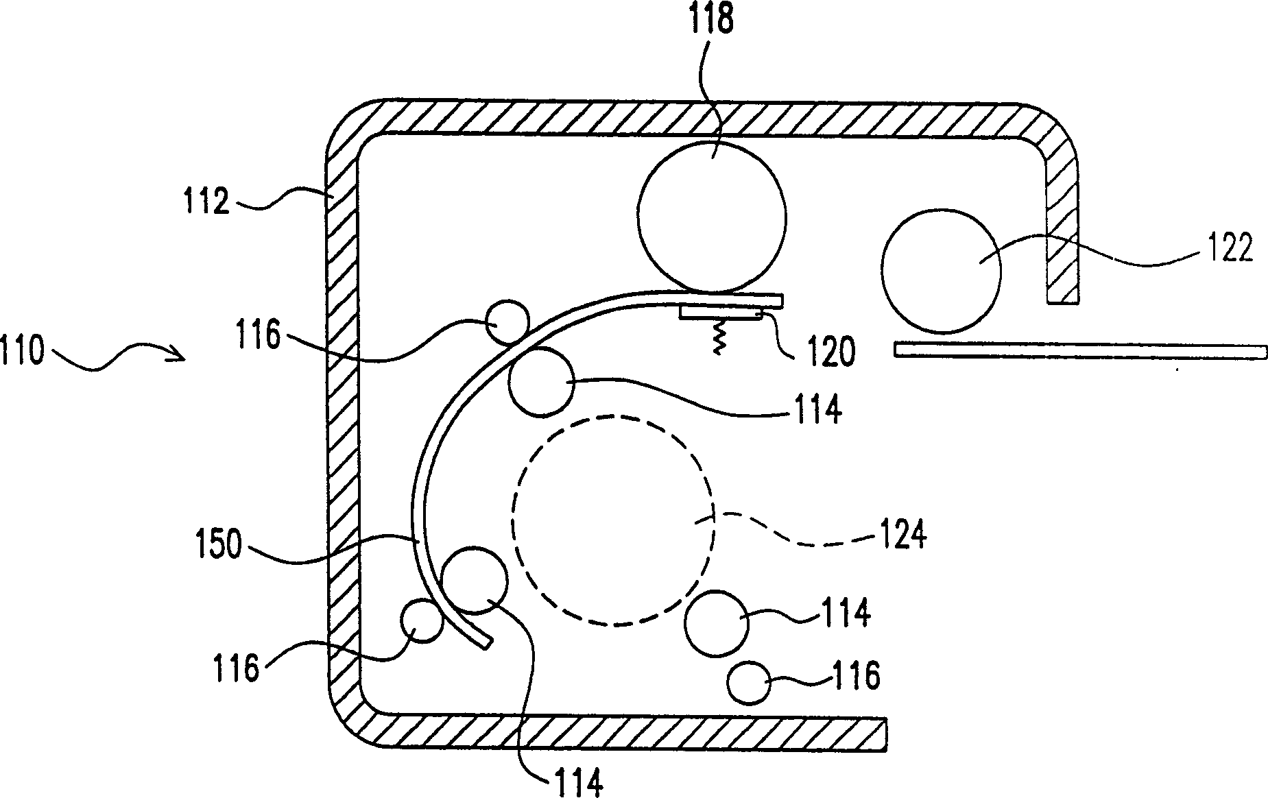
A document transmission and scanning mechanism technology, applied in the direction of electrical components, image communication, etc., can solve the problems of high height of the document transmission mechanism 110, difficult to design, complicated mechanism design and coordination, etc.

Inactive Publication Date: 2004-05-26
UMAX DATA SYST
View PDF0 Cites 0 Cited by
  • Summary
  • Abstract
  • Description
  • Claims
  • Application Information

AI Technical Summary

Problems solved by technology

[0004] In the above-mentioned document conveying mechanism 110, since multiple groups of conveying rollers 114a, 114b, 114c and idler wheels 116a, 116b, 116c are arranged around the motor 124 in pairs respectively, and in order to pass through the separating rollers 118 and separate When the documents between the boards 120 can smoothly move between the transmission roller 114a and the idler 116a, the height of the distribution roller 118 and the distribution board 120 must be higher than the position of the transmission roller 114a and the idler 116a. Therefore, the arrangement positions of the motor 124, the separating roller 118, the separating plate 120, the conveying rollers 114a, 114b, 114c and the idler wheels 116a, 116b, 116c as described above will cause the height of the document conveying mechanism 110 to be very high.
Furthermore, since the file transfer mechanism 110 needs to use multiple sets of transfer rollers 114a, 114b, 114c and idle wheels 116a, 116b, 116c to transfer the file 150, the design of the mechanism is very complicated and difficult to design.
In addition, since the multiple sets of transport rollers 114a, 114b, 114c and idler wheels 116a, 116b, 116c only touch a very small area of ​​the document 150 when the document 150 is being transported, it is easy to cause poor transmission of the document 150, and even cause the document 150 to be stuck in the What happens inside the file transfer mechanism 110

Method used


Image

  • Document transported typed scanning mechanism
  • Document transported typed scanning mechanism
  • Document transported typed scanning mechanism

Examples


Embodiment Construction

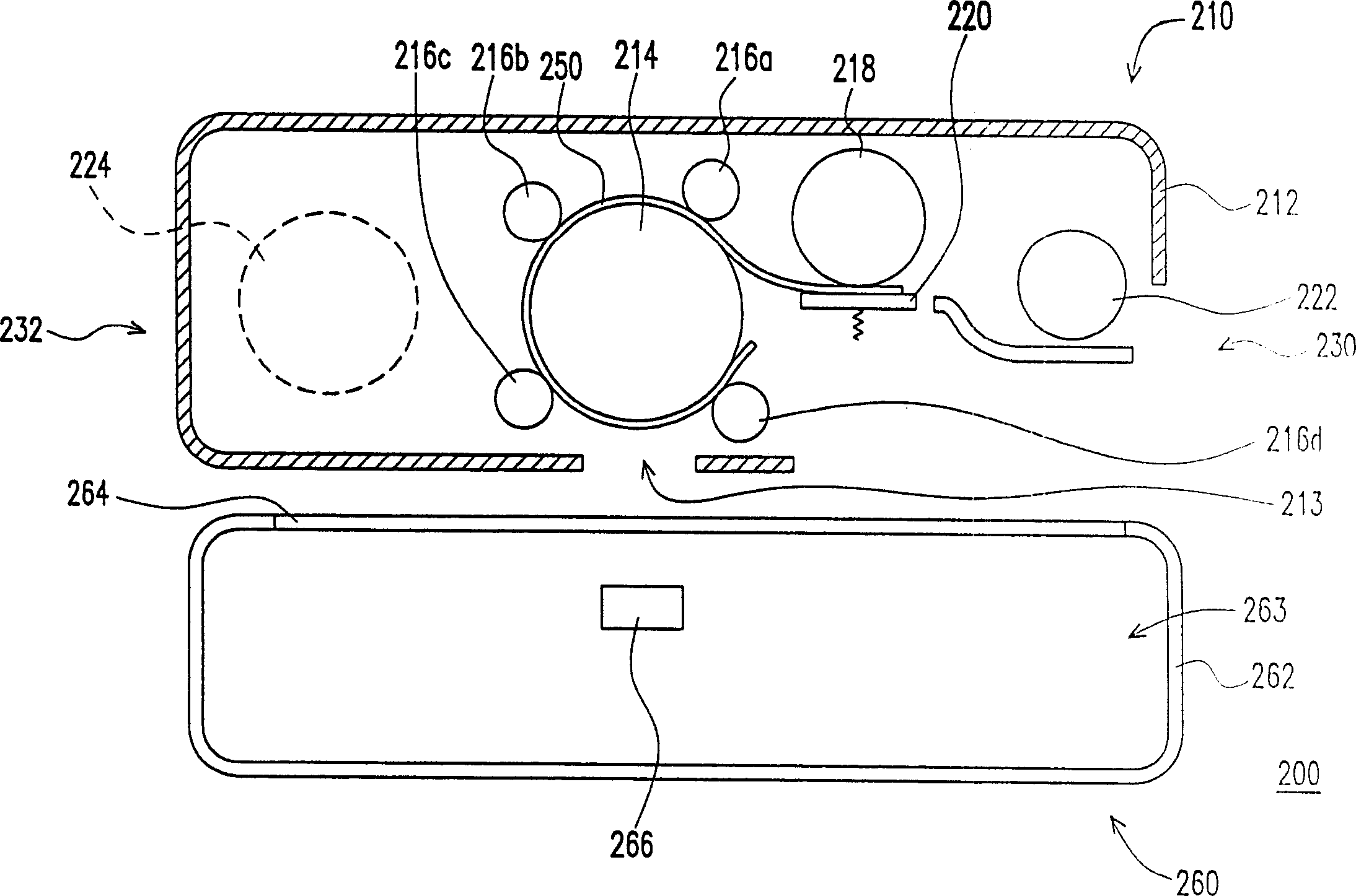
[0072] Please refer to figure 2 , which is a structural schematic diagram of a file transport scanning mechanism according to a first preferred embodiment of the present invention. The file transfer type scanning mechanism 200 includes a file transfer mechanism 210 and a scanner 260, the file transfer mechanism 210 is located on the scanner 260, and the file transfer mechanism 210 is used to transfer a document 250, and the scanner 260 is used to scan and transfer to the file Document 250 in transport mechanism 210 .

[0073] The document delivery mechanism 210 includes a document delivery mechanism housing 212, a transport roller 214, four subordinate rollers 216a, 216b, 216c, 216d, a split roller 218, a split plate 220, a file loading roller 222 and a motor 224 . The file transfer mechanism 210 has a first side 230 and a corresponding second side 232, the document 250 enters the file transfer mechanism 210 from the first side 230, and the motor 224 is located inside the f...


PUM


Abstract

The scanning mechanism includes at least a mechanism for transporting document and a scanning module. The document transportation mechanism includes at least a transmission roller and multiple supporting rollers. The multiple supporting rollers are leaned on the transmission roller, and document is passed through between the transmission roller and multiple supporting rollers. The scanning module scans the document transferred in the document transportation mechanism. The scanning module includes at least one optical sensing assembly to pick up image of document.

Description

technical field [0001] The invention relates to a document conveying scanning mechanism, and in particular to a document conveying scanning mechanism capable of effectively reducing the height of the document conveying mechanism. Background technique [0002] Please refer to figure 1 , which is a schematic diagram of a known file transfer mechanism. The document transmission mechanism 110 comprises a document transmission mechanism housing 112, three transmission rollers 114a, 114b, 114c, three idle wheels 116a, 116b, 116c, a split roller 118, a split plate 120, a file loading roller 122 and A motor 124. The motor 124 is located inside the document transport mechanism housing 112 . The document loading roller 122 is also located inside the document transport mechanism housing 112 for loading a document 150 . The separation roller 118 and the separation plate 120 are all configured in the inside of the file transfer mechanism housing 112, and the separation roller 118 wil...

Claims


Application Information

Patent Timeline
IPC IPC(8): H04N1/00
Inventor 江淑雅
Owner UMAX DATA SYST
Why Eureka
Try Eureka