
Micro mirror box for scan probe microscope

A scanning probe and microscope technology, applied in the microscope field, can solve the problems of high vacuum, complex structure, difficult temperature, etc., and achieve the effect of low production cost, small volume, and improved vacuum degree

Inactive Publication Date: 2006-06-07
陆轻锂
View PDF0 Cites 12 Cited by
  • Summary
  • Abstract
  • Description
  • Claims
  • Application Information

AI Technical Summary

Problems solved by technology

[0003] The purpose of the present invention is to overcome the shortcomings of the above-mentioned scanning probe microscope, such as complex structure, too large volume, difficult to draw a high vacuum, and difficult to lower the temperature, and to design a structure that is simple and reasonable, and has low production cost. Scanning Probe Microscope Miniature Box for Low, Small Size, Portability, Ease of High Vacuum and / or Reduced Temperature, and Reduced Noise

Method used


Image

  • Micro mirror box for scan probe microscope
  • Micro mirror box for scan probe microscope
  • Micro mirror box for scan probe microscope

Examples


Embodiment Construction

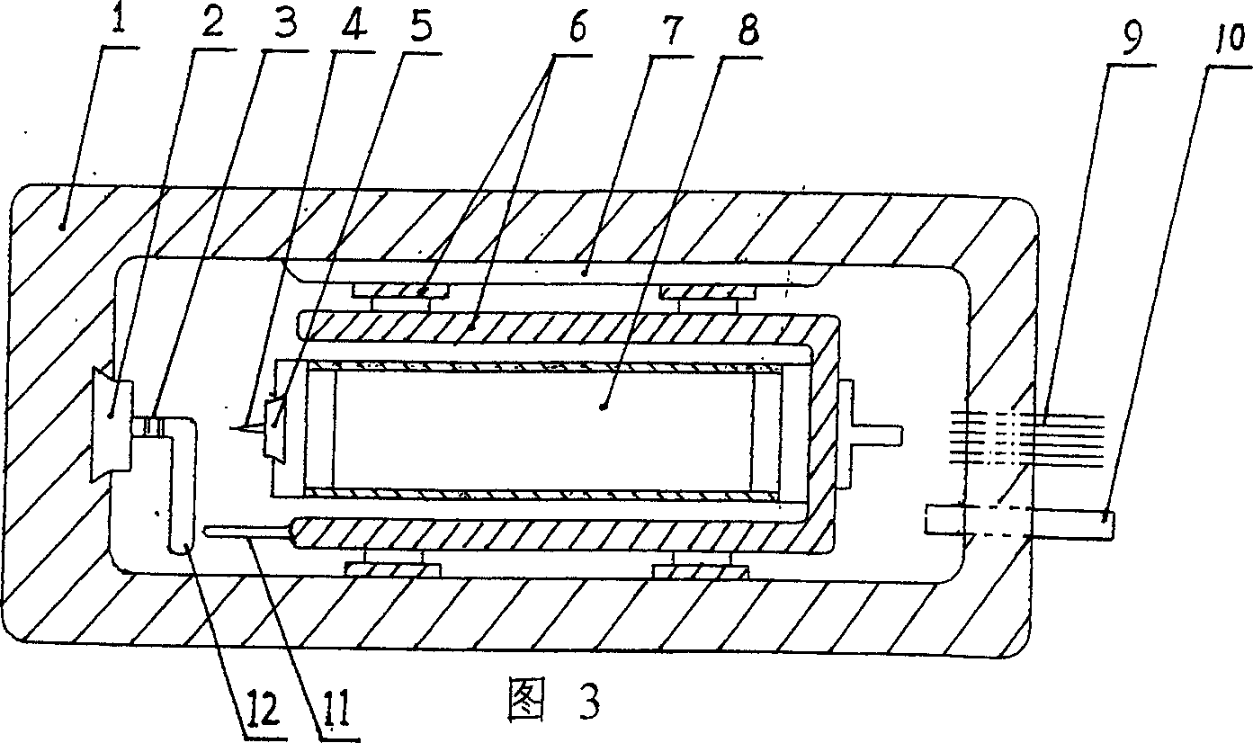
[0020] See attached figure 1 , the sample seat 2 in the figure is set on the inner wall of the box body 1, the communication interface 9 and the air extraction hole 10 are set on the box body 1, the electrostrictive stepper 6 is pressed into the box body 1 through the spring leaf 7, and the electrostrictive stepper 6 is pressed into the box body 1. The rear end of the telescopic scanning tube 8 is fixed on the electrostrictive stepper 6, the probe frame 5 is arranged on the front end of the electrostrictive scanning tube 8, the probe 4 is mounted on the probe frame 5, the signal lines of the probe 4 and The control line of the electrostrictive stepper 6 and the control line of the electrostrictive scanning tube 8 are connected to the communication interface 9 . When in use, the sample 3 to be tested is installed on the sample seat 2 in the box body 1, the probe 4 used is installed on the probe frame 5, and the sealed box cover is covered. The air extraction hole 10 is connect...


PUM


Abstract

The micro mirror box for scanning probe microscope includes an electrostrictive stepped unit, an electrostrictive scanning tube, a box, a box cover, a sample seat, a probe, a probe rack, a communication interface and a pumping hole, as well as a sample cutting push rod and an auxiliary probe. The probe and the auxiliary probe may be available probe for scanning tunnel microscope, atomic force microscope and / or magnetic microscope. The present invention has the features of simple and reasonable structure, low cost, small size, etc. and is favorable to raising vacuum degree, lowering temperature, raising S / N ratio, raising signal stability, etc. It may be used for vacuum cutting, vacuum probe replacement and scanning with different kinds of probe, in scanning tunnel microscope, atomic force microscope, magnetic microscope and their combination.

Description

technical field [0001] The invention relates to a scanning probe microscope, in particular to a scanning probe microscope miniature mirror box suitable for ultra-low temperature, ultra-high vacuum and ultra-low noise, belonging to the field of microscopes. Background technique [0002] Since the invention of the first scanning probe microscope---Scanning Tunneling Microscope (STM) in 1982, with its extremely high resolution (atomic resolution) and rich physical information (electron cloud density information on the sample surface), As well as the low cost, it has been widely used immediately. Soon, there was an atomic force microscope, a magnetic force microscope, and so on. They use electrostrictive devices such as electrostrictive steppers and electrostrictive scanning tubes, and use corresponding probes to scan the surface of the sample to measure the surface properties of different types of samples, collectively referred to as scanning probe microscopes. It has now gro...

Claims


Application Information

Patent Timeline
IPC IPC(8): G01N1/06G01N1/28G01Q70/00
Inventor 陆轻锂陆轻铱高峰陆轻铀
Owner 陆轻锂
Learn More