
Electronic balance

一种电子天平、电流的技术,应用在使用电磁平衡的称重设备、仪器、测量装置等方向,能够解决不能实现高速和高稳定性的测量、高精度变坏等问题,达到减少灵敏度的变化或线性度的变化、防止灵敏度的变化或线性度的变化的效果

Inactive Publication Date: 2006-06-07
SHIMADZU SEISAKUSHO CO LTD
View PDF2 Cites 18 Cited by
  • Summary
  • Abstract
  • Description
  • Claims
  • Application Information

AI Technical Summary

Problems solved by technology

When this happens, the sensitivity and linearity of the electronic balance will change from those at the time of electronic balance adjustment and operations related to it, high precision will deteriorate or high speed and high stability cannot be achieved due to external vibrations. Measurement
This causes problems especially in the case of electronic balances with short distances from the fulcrum or high-sensitivity electronic balances, the consequences of which are considerable

Method used


Image

  • Electronic balance
  • Electronic balance
  • Electronic balance

Examples


Embodiment Construction

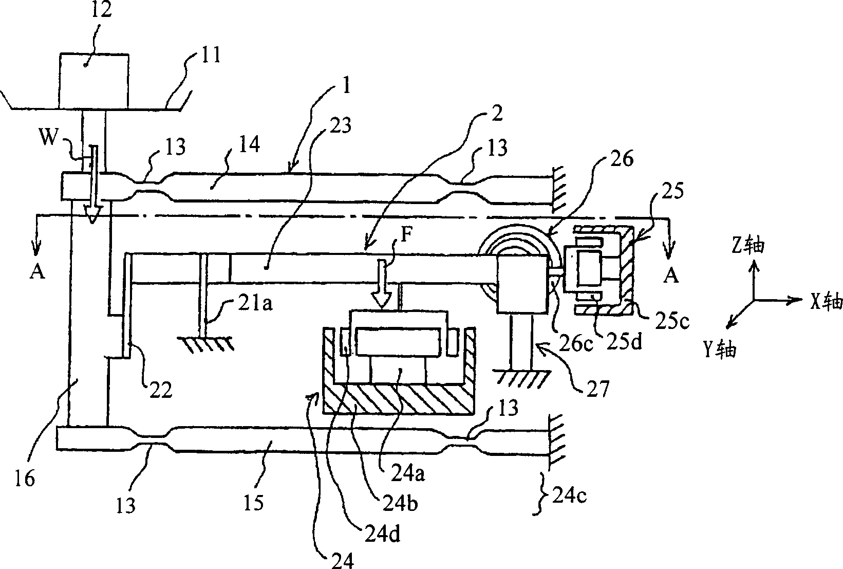
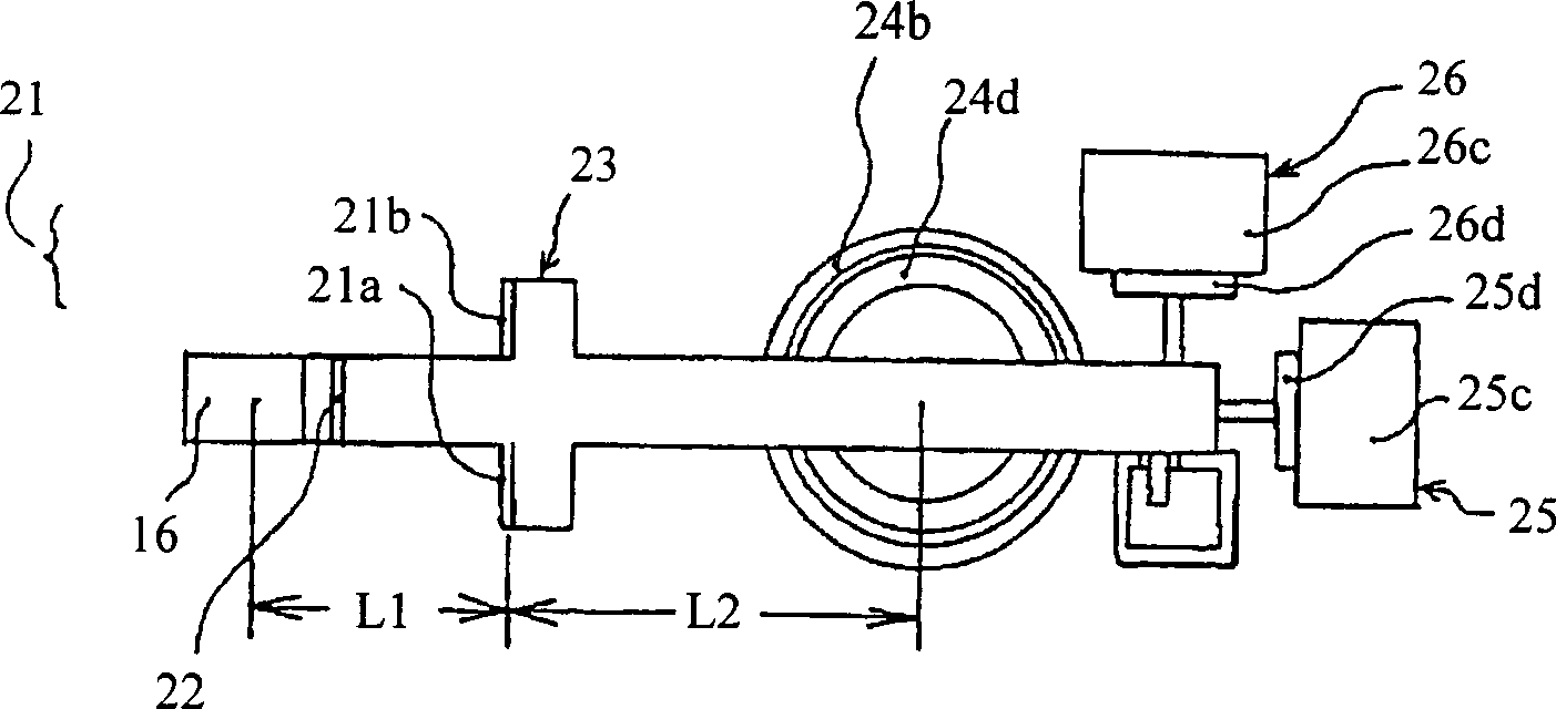
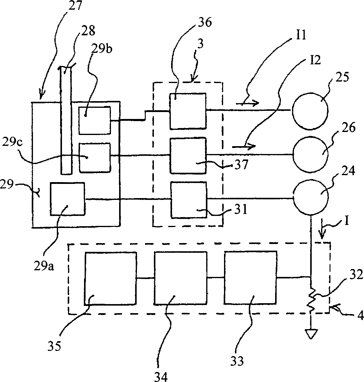
[0019] The electronic balance of the present invention will be described in detail below through examples. Figure 1A A configuration diagram showing a partial cross section shows the configuration of the electronic balance according to the present invention. Figure 1B showing along Figure 1A A cross-sectional view of an electronic balance cut along line A-A. figure 2 is a block diagram showing a method for controlling the load balancing mechanism 2 ( Figure 1A ) of the control section 3 and the display section 4 for displaying its measured values.

[0020] Figure 1 and figure 2 As shown, the electronic balance includes a load transmission mechanism 1 , a load balancing mechanism 2 , a control part 3 and a display part 4 . The load transfer mechanism 1 transfers a load-on-pan load (load-on-pan) W of a measured object 12 mounted on a measurement pan 11 to a load balance mechanism 2 as a vertical load. The load balancing mechanism 2 balances an electromagnetic force F (me...


PUM


Abstract

The invention discloses an electronic balance. The electronic balance of the electromagnetic force balance type includes an electromagnetic force generator, a PID controller and a three-axis direction position detector, and the electromagnetic force generator is used to apply electromagnetic force to control the balance beam in the longitudinal direction (X axis) and the level perpendicular to it direction (Y-axis), the PID controller is used to control the electromagnetic force generator through PID control, and the three-axis direction position detector is used to detect the displacement of the balance beam in the three directions of X, Y-axis direction and gravity direction.

Description

technical field [0001] The present invention relates to an electronic balance of an electromagnetic force balance type for measuring a load by setting a support point to balance the load and an electromagnetic force applied to a balance beam. More particularly, the present invention relates to an electronic balance having a short distance from a fulcrum or an electronic balance having high precision. Background technique [0002] In general, an electronic balance of the electromagnetic force balance type is configured such that an electromagnetic force generated by an electromagnetic force generator is applied to a balance beam engaged with a measuring pan, and the balance beam is balanced with a load applied to the measuring pan. The displacement of the balance beam is detected by the position (displacement) sensor, and the amount of current supplied to the coil of the electromagnetic force generator is controlled by the servo mechanism, so as to obtain the detection result...

Claims


Application Information

Patent Timeline
Patent Type & Authority Applications(China)
IPC IPC(8): G01G7/02G01G7/00
CPCG01G7/045
Inventor 佐藤毅田村公利岛内邦夫
Owner SHIMADZU SEISAKUSHO CO LTD
Learn More