
Cylinder head cap for a cylinder head of an internal combustion engine and process for the manufacture of a cylinder head cap

A technology of internal combustion engine cylinder and cylinder head cover, which is applied to the sealing device, mechanical equipment, transportation and packaging of the engine, etc., to achieve the effects of reducing distortion problems, high molding freedom, and simple composition

Inactive Publication Date: 2006-06-07
FITTERMOGU SEALING SYST BLEITEN GMBH
View PDF1 Cites 3 Cited by
  • Summary
  • Abstract
  • Description
  • Claims
  • Application Information

AI Technical Summary

Problems solved by technology

This transmission of vibrations via the sealing lip of the ring seal protruding from the end face cannot be avoided, since there is always the risk that, due to the high tightening force, the section of the cylinder head cover comes into direct contact with the cylinder head

Method used


Image

  • Cylinder head cap for a cylinder head of an internal combustion engine and process for the manufacture of a cylinder head cap
  • Cylinder head cap for a cylinder head of an internal combustion engine and process for the manufacture of a cylinder head cap
  • Cylinder head cap for a cylinder head of an internal combustion engine and process for the manufacture of a cylinder head cap

Examples


Embodiment Construction

[0021] The same components in the figures have the same reference symbols.

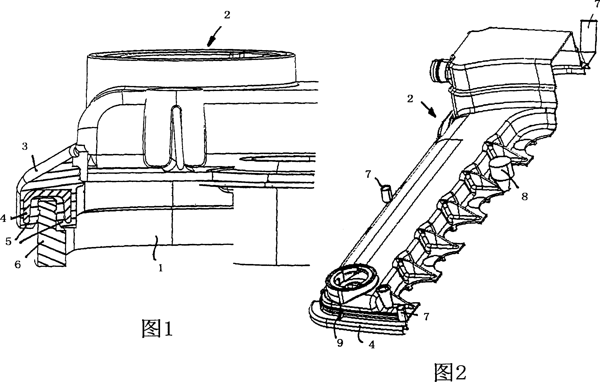
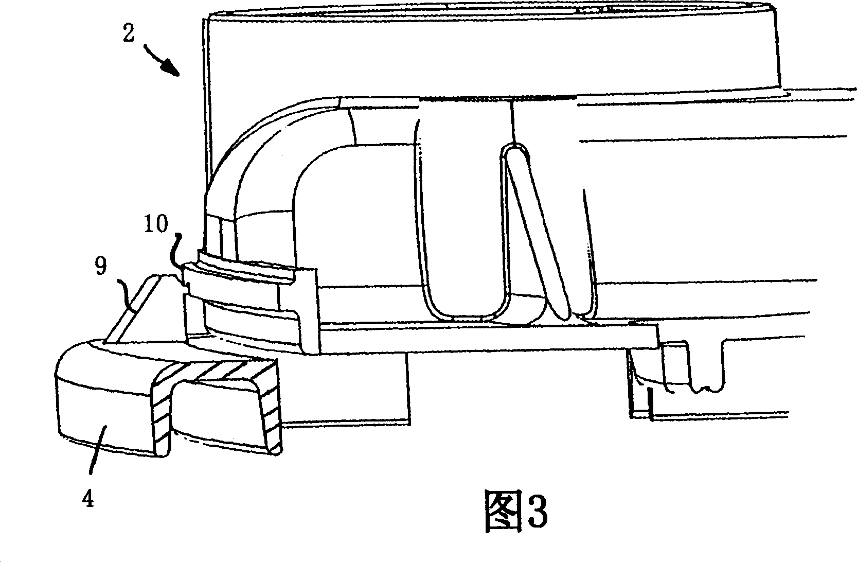
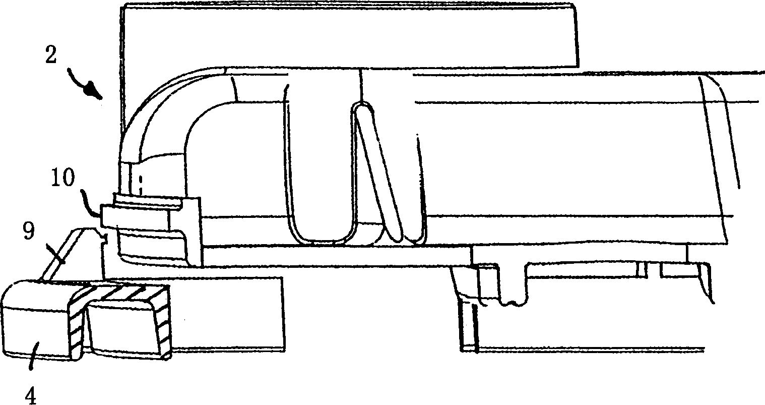
[0022] FIG. 1 shows the upper section of a cylinder head 1 of an internal combustion engine with a cylinder head cover 2 placed thereon. In order to obtain a flow-tight closure between the cylinder head cover 2 and the cylinder head 1 produced as a plastic moulding, there is an annular seal 3 distributed in the region of the outer edge of the cylinder head cover 2 , which is injection-moulded in accordance with the purpose Cylinder head cover 2 on. Inserted in the sealing body of the seal 3 is a likewise annular support ring 4 which consists of the same plastic material as the cylinder head cover 2 . The support ring 4 is U-shaped, wherein the opening in the support ring faces downwards. The support ring 4 is completely surrounded by the material of the seal 3 during the injection molding process in which the seal elastomer is injected onto the support ring 4 . Due to the U-shape of the support rin...


PUM


Abstract

The invention relates to a cylinder head cover for a cylinder head of an internal combustion engine. The cylinder head cover has a seal for sealing between the cylinder head cover and the cylinder head. A stabilizing core is inserted into the seal. The stabilizing core is completely surrounded by sealing material. In this way it is ensured that the stabilizing core does not come into direct contact with the cylinder head cover nor with the cylinder head. This effectively decouples vibrations.

Description

technical field [0001] The invention relates to a cylinder head cover for a cylinder head of an internal combustion engine according to the preamble of claim 1 and a method for producing a cylinder head cover according to the preamble of claim 5 or 8 . Background technique [0002] Patent document DE 197 38 275 A1 describes a cylinder head cover for a cylinder head of an internal combustion engine, which is fastened to the cylinder head by means of bolts, wherein, for sealing between the cover and the cylinder head, there are annularly distributed seals, buckles On or injection-moulded on the outwardly protruding flange of the cylinder head cover. The sealing lip of the seal protrudes beyond the end face of the cylinder head cover, so that when the cylinder head cover is placed and installed, the sealing lip lies on the adjacent surface of the cylinder head and acts as a kind of contact between the cylinder head and the cylinder head cover. The hermetic action of the flow s...

Claims


Application Information

Patent Timeline
Patent Type & Authority Applications(China)
IPC IPC(8): F02F7/00B29C45/14F02F11/00
CPCF02F7/006F02F11/002Y10S277/916
Inventor 拉尔夫·萨拉马
Owner FITTERMOGU SEALING SYST BLEITEN GMBH
Learn More