
Separable toilet

A separate, toilet technology, used in flushing equipment with water tanks, sanitary equipment for toilets, flushing toilets, etc., can solve the problems of difficult cleaning, difficult to remove, and high costs, achieve high-efficiency solid-liquid separation, and prevent increase. Large, the effect of preventing transportation and installation costs

Inactive Publication Date: 2006-06-07
ミリオン商事
View PDF0 Cites 13 Cited by
  • Summary
  • Abstract
  • Description
  • Claims
  • Application Information

AI Technical Summary

Problems solved by technology

[0008] However, in the separate toilets described in Patent Documents 1 and 2, the distance from the toilet to the fermentation tank 3 and the excrement treatment tank 6 where the solid components of excrement and urine are dropped is long, so the distance from the toilet has to be increased. The height from the toilet setting surface (ground, floor surface) to the toilet
As a result, the size of the toilet increases, and the transportation and installation costs increase
In particular, considering that it is a nursing toilet used near the bed, the height from the floor to the toilet seat cannot be controlled to about 38cm, which is the most suitable for the nursing object, so it cannot be used.
[0009] Also, when disposing of the toilet paper used when using feces, it is generally believed that it will adhere to the piping between the toilet and the fermentation tank (stool treatment tank), but it is described in the above-mentioned Patent Documents 1 and 2 In the separate toilet, it is difficult to remove the pipe because it is difficult for hands or cleaning tools to reach from the top (toilet side).
At this time, only the toilet paper attached to the pipe is washed with clean water, but the toilet paper flows through the pipe and flows into the urine receiving container, which may clog the pipe leading from the urine receiving container to the purification tank (urine disposal tank), etc.
[0010] When the piping from the urine receiving container is blocked, the urine receiving container is directly cleaned to remove the blockage, but in the separate type toilet described in the above-mentioned patent document 1, in order to expose the urine receiving container 35, it is necessary to remove the toilet 31. , the first defecation tube 32, the second defecation tube 33, and the cylinder 34 are all removed.
In addition, in the separate type toilet described in the above-mentioned patent document 2, even if the toilet 2 is taken off, because the diameter of the upper part of the urine receiving container 4 is reduced, the gap with the defecation pipe 5 is narrow, and there are also hand or The problem that the cleaning tool cannot reach the bottom of the urine receiving container 4 and cleaning is difficult
[0011] In addition, in the toilets described in the above-mentioned patent documents 1 and 2, there is a structure in which the urine receiving container and the defecation pipe passing through the central part are assembled up and down in a single body. Since the seams need to be sealed and the sealing performance must be checked. , so the manufacturing cost is high, and there may be leakage from the seam due to long-term aging, etc.
In addition, in the above-mentioned patent document 1, the connecting portion of the discharge port 31a and the main body of the toilet 31 is constricted, and in the above-mentioned patent document 2, since the urine receiving container 4 is formed in the shape of a pot whose upper part is constricted , so it cannot be made by a simple forming die, so the cost becomes higher

Method used


Image

  • Separable toilet
  • Separable toilet
  • Separable toilet

Examples


Embodiment Construction

[0032] Hereinafter, embodiments of the present invention will be described with reference to the drawings.

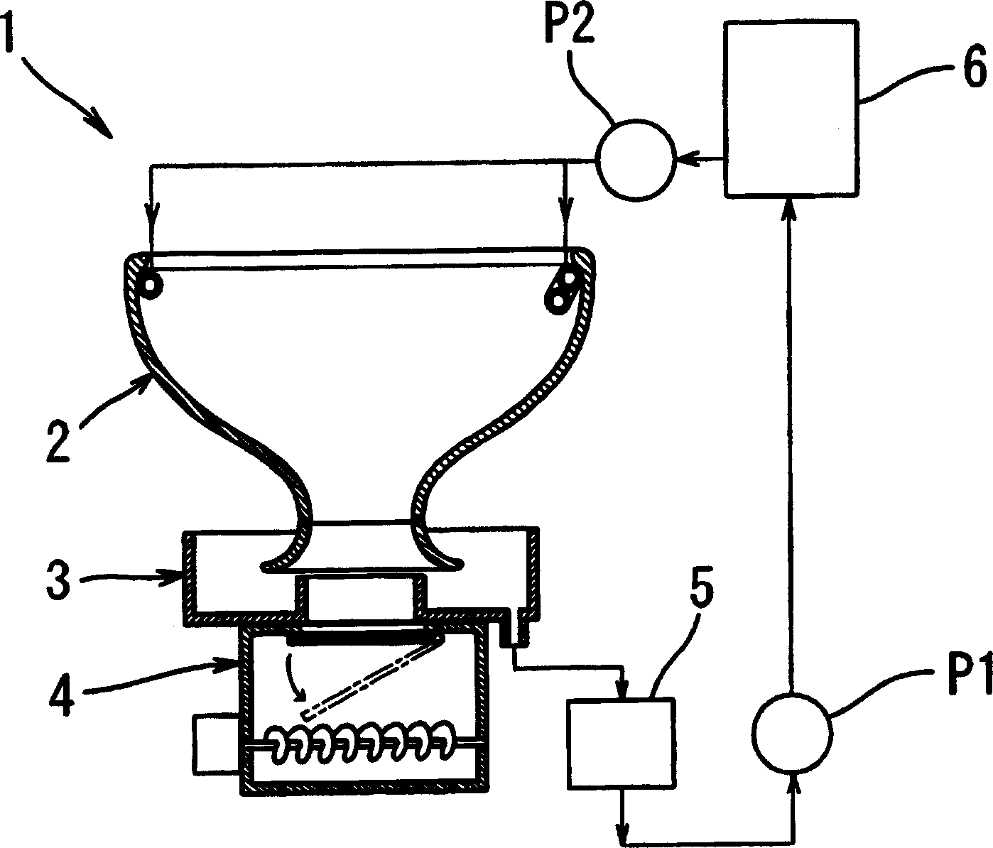
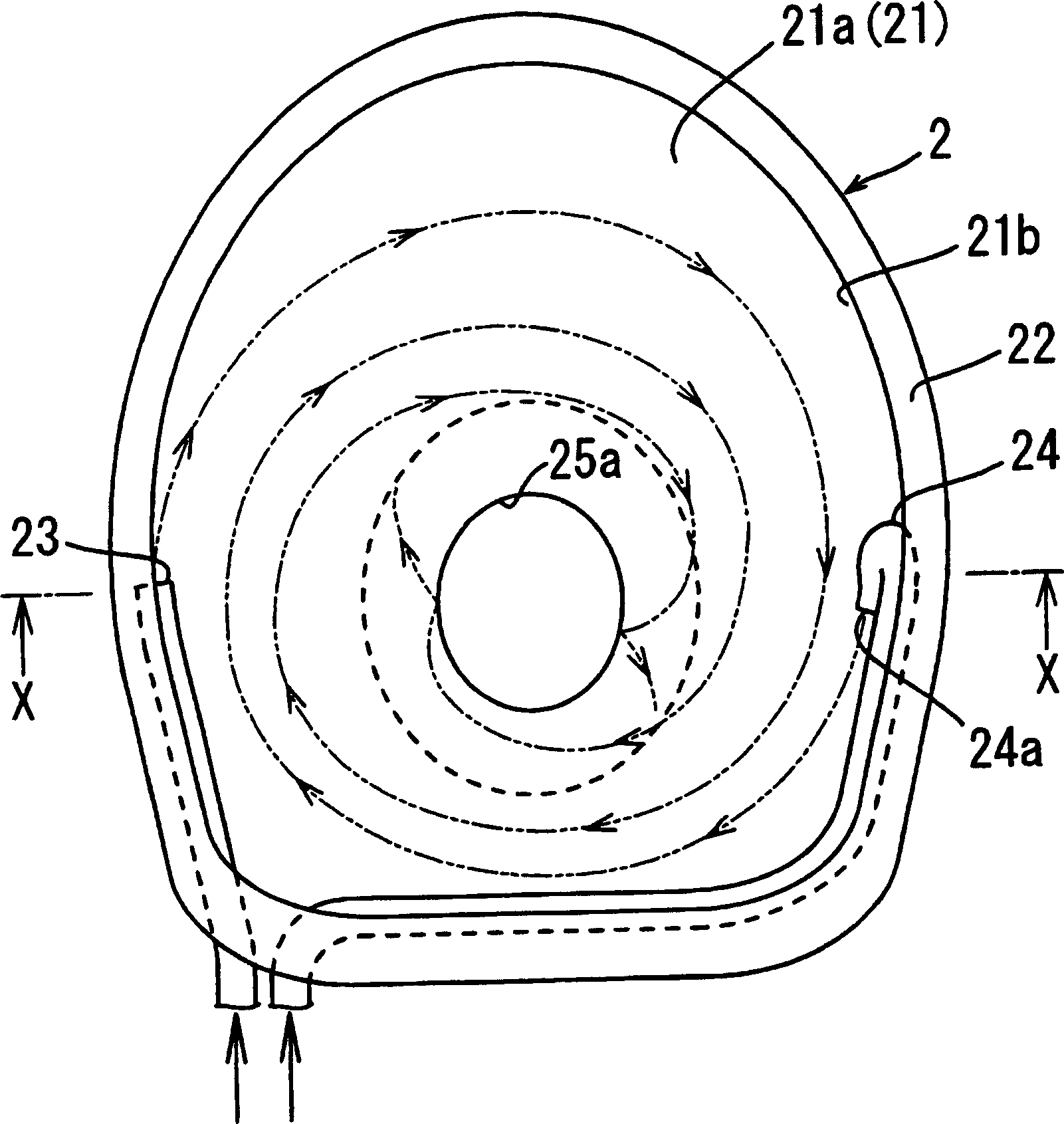
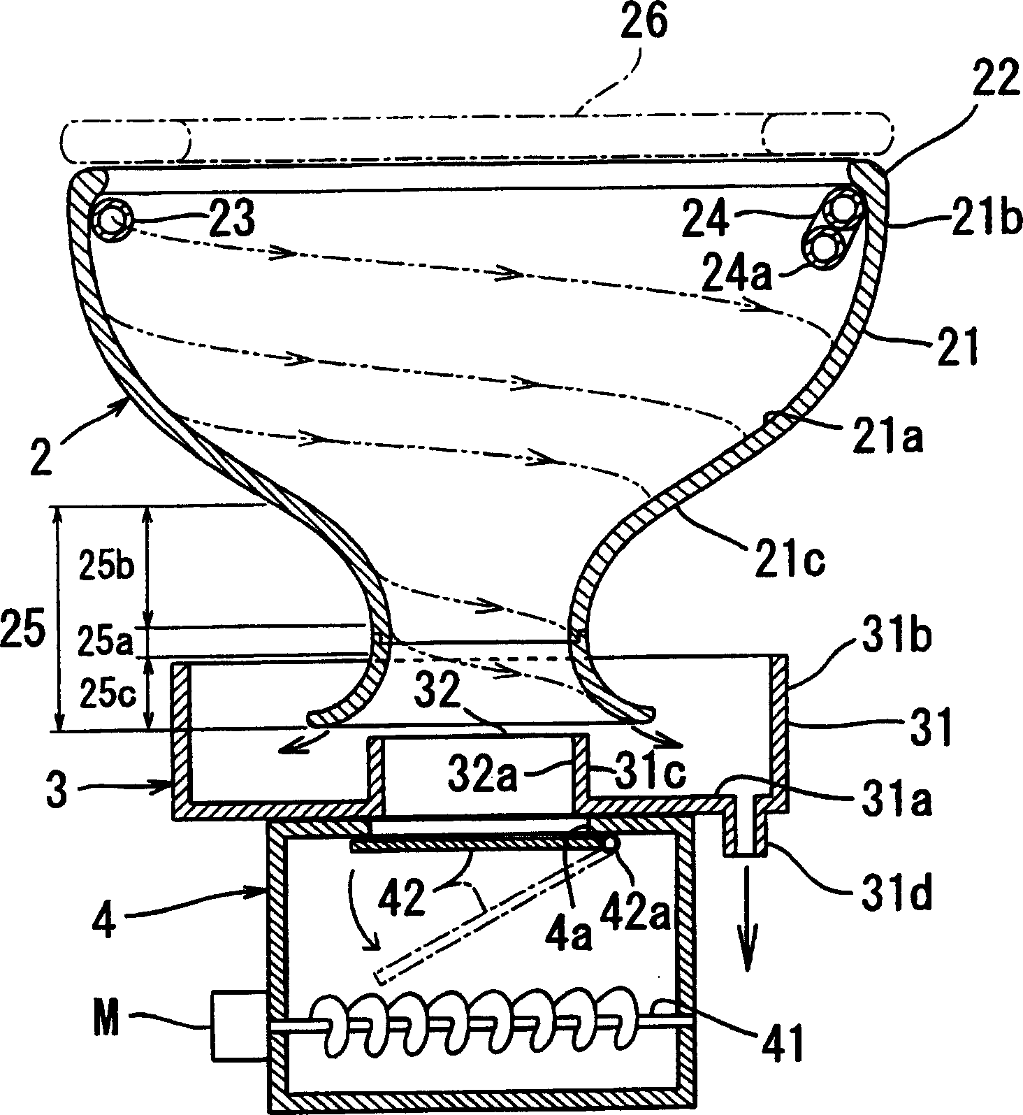
[0033] Figure 1 to Figure 5 An example of an embodiment of the invention is shown. figure 1 It is a schematic block diagram showing the separate type toilet of this embodiment. figure 2 A top view of a toilet showing a split toilet. image 3 is equivalent to figure 2 The X-X section of , showing the toilet, the solid-liquid separator and the solid component receiving part arranged below it. Figure 4 It is a figure explaining the manufacturing method of the discharge pipe formed in the bottom part of a toilet. Figure 5 It is a figure explaining the structure and manufacturing method of a solid-liquid separator. Also, in figure 1 as well as image 3 In , although the toilet is described in a suspended state, it is actually supported and fixed by an unillustrated support table and fixing tools. In addition, although the solid-liquid separator is described in a...


PUM


Abstract

The invention discloses a separate toilet, which is composed of a throttling portion reduced to the smallest diameter, an upper expansion portion that expands from the throttle portion upward in a trumpet shape, and a lower expansion portion that expands from the throttle portion downward in a trumpet shape. The discharge pipe is integrally formed at the bottom of the toilet main body; a solid-liquid separator having a container-shaped liquid component receiving part and a cylindrical solid component receiving part penetrating up and down is provided directly below it; the solid component of excrement and urine is separated from The throttling part drops directly to the solid component receiving part, and the liquid component drops directly to the liquid component receiving part through the lower expansion part. Therefore, it is possible to suppress the height reduction from the toilet mounting surface to the toilet bowl, and even when toilet paper is attached to the piping provided below the toilet bowl, it can be easily removed.

Description

technical field [0001] The present invention relates to a separate type toilet for separating excrement and urine excreted on the excrement and urine receiving surface of the toilet into solid components and liquid components. Background technique [0002] Conventionally, among temporary toilets used in parks, construction sites, etc., separate toilets have been proposed in which excrement and urine excreted in the toilet are separated into solid components and liquid components, and fermented and purified by microorganisms, respectively. Accordingly, the solid content can be used for fertilizers and the like, while the liquid content can be used as flushing water for flushing the toilet (see Patent Document 1 and Patent Document 2). [0003] In the separate type toilet shown in patent document 1, the discharge port 31a provided in the bottom part of the toilet 31 expands downward and is formed. The liquid component of feces and urine excreted in the toilet 31 drips from th...

Claims


Application Information

Patent Timeline
Patent Type & Authority Applications(China)
IPC IPC(8): E03D5/014E03D9/10E03D5/016E03D11/02
Inventor 川嶋嘉己
Owner ミリオン商事
Learn More