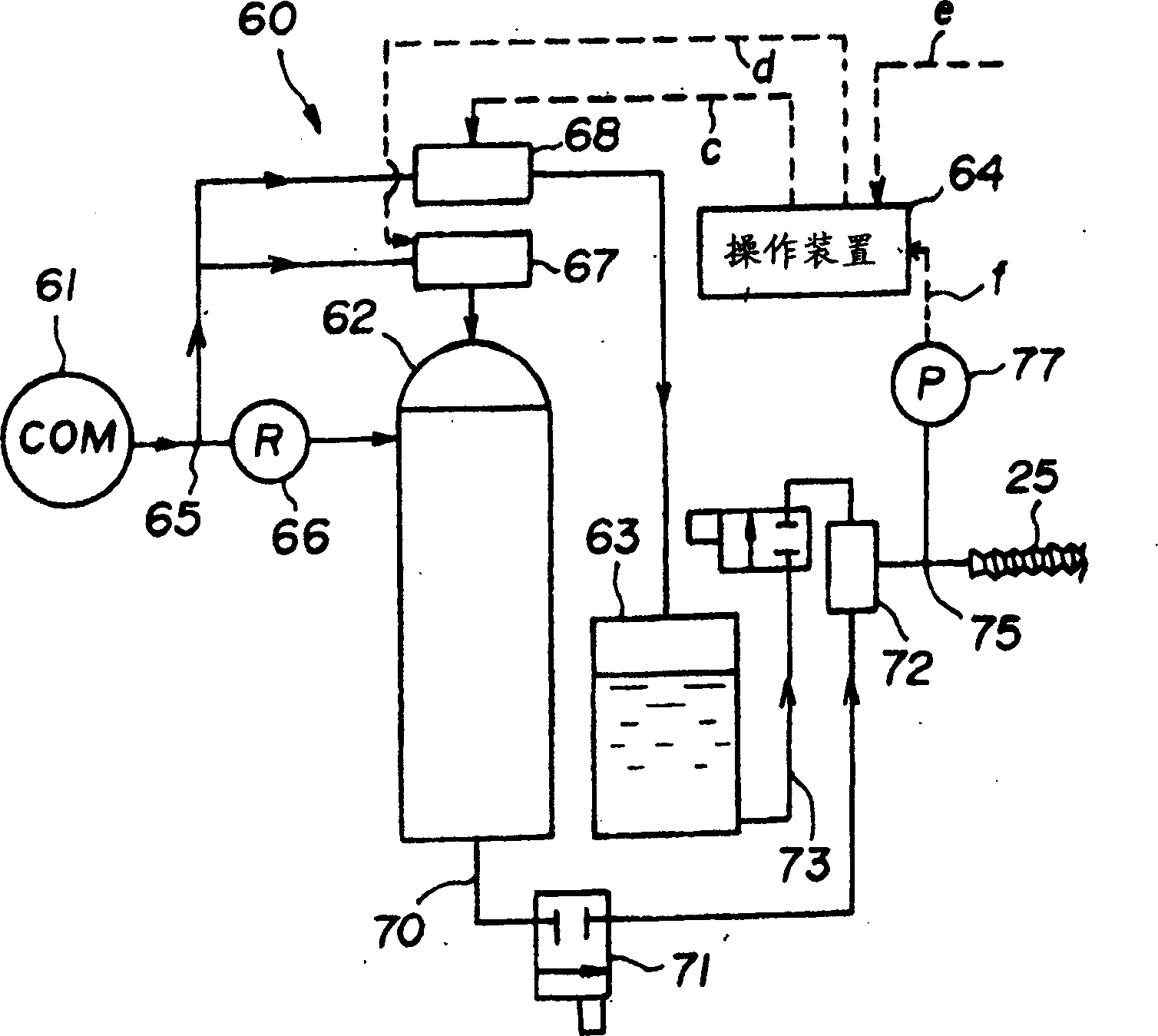
Method of coating lubricant in metallic injection machine

一种注射成形机、分型剂的技术,应用在在金属注射成形机中涂覆分型剂领域,能够解决增加维修频率、操作环境退化、模制件质量下降等问题,达到简化模具结构的效果

Active Publication Date: 2006-06-07
THE JAPAN STEEL WORKS LTD
View PDF1 Cites 4 Cited by
  • Summary
  • Abstract
  • Description
  • Claims
  • Application Information

AI Technical Summary

Problems solved by technology

However, according to the principle of the coating method, there are problems caused by a decrease in mold temperature due to water, a decrease in the quality of molded parts due to the distribution of a water-soluble release agent, degradation of the operating environment, and other problems
[0010] As described above, according to the prior art mold release agent coating method or mold device, the pressure inside the cavity cannot be maintained to the required pressure, so there is a problem that metal molded parts with thin wall thickness cannot be molded, and the flow direction of the molten metal cannot be molded. Problems with metal moldings or similar moldings having long overall lengths
In addition, in accordance with the structure having a structure capable of maintaining the pressure in the cavity to a desired pressure value, a metal path opening / closing member is provided, so that there are problems in that the mold structure is complicated, maintenance frequency is increased, and opening / closing operations are required

Method used


Image

  • Method of coating lubricant in metallic injection machine
  • Method of coating lubricant in metallic injection machine
  • Method of coating lubricant in metallic injection machine

Examples


Embodiment Construction

[0019] A metal element itself having a melting point equal to or lower than 700° C. or an alloy based on the metal is referred to as a metal raw material of the present invention. As practical examples, for example aluminium, magnesium, zinc, tin, lead, bismuth, terbium and similar elements may be chosen, in particular aluminium, magnesium, lead, zinc, bismuth, tin itself and alloys based on these metals are preferred. Any metal raw material is a metal element or alloy that can be melted in a heating cylinder by heat supplied from the outside and shaped by injection into a mold product cavity. Although the melting point of copper is 1085°C and much higher than 700°C, the melting point of copper alloys such as copper alloys used for brazing is equal to or less than 700°C, and copper alloys also constitute objects of metal raw materials according to the present invention. Furthermore, according to the invention, the object of the invention is also achieved by simultaneously addi...


PUM


Abstract

The movable mold is fastened to the fixed mold, and the relationship between the contact force and the tightness of the injection nozzle and the injection hole of the fixed mold is investigated. Through the contact force, the injection nozzle and the injection hole of the fixed mold are brought into pressure contact to achieve a predetermined tightness , and apply the release agent by predetermined pressure. In this case, one end of the cavity is open or the air is vented from this end, as required. The release agent is applied as a mist by mixing with compressed air. In addition, the release agent is applied by keeping constant the pressure difference between the pressure applied to the release agent and the internal pressure of the cavity and the pressure difference between the pressure of the compressed gas and the internal pressure of the cavity.

Description

technical field [0001] The present invention relates to a method of applying a parting agent in a metal injection molding machine comprising a fixed mold and a movable mold, and wherein a cavity is formed at a parting surface of the mold when the movable side mold is fastened to the fixed side mold On one side, and the molten metal is injected from the injection nozzle to fill the cavity through the filling hole of the sprue hole, the runner groove, the gate hole and the like, thereby providing a metal molded part, and before injecting and filling the molten metal The release agent is applied to the surfaces of the fill holes and mold cavities. Background technique [0002] As a molding method for providing a metal product from a low melting point metal material of aluminum alloy, magnesium alloy, zinc alloy or the like, the thixotropic molding method is known. According to the method, when the alloy raw material is agitated in the state of solid / liquid coexistence, the for...

Claims


Application Information

Patent Timeline
Patent Type & Authority Applications(China)
IPC IPC(8): B22D17/00
CPCB22D17/00B22D17/2007
Inventor 武谷健吾冲本晋一
Owner THE JAPAN STEEL WORKS LTD
Why Eureka
Try Eureka