Eureka AIR delivers breakthrough ideas for toughest innovation challenges, trusted by R&D personnel around the world.

Controlling ion populations in a mass analyzer

A mass analyzer and ion technology, applied in the field of ion number, to eliminate space charge effect and improve sensitivity

Active Publication Date: 2006-05-24
THERMO FINNIGAN
View PDF0 Cites 10 Cited by
  • Summary
  • Abstract
  • Description
  • Claims
  • Application Information

AI Technical Summary

Problems solved by technology

This used to be a relatively minor problem, only drifting the mass by a few tens of ppm

Method used


Image

  • Controlling ion populations in a mass analyzer
  • Controlling ion populations in a mass analyzer
  • Controlling ion populations in a mass analyzer

Examples


Embodiment Construction

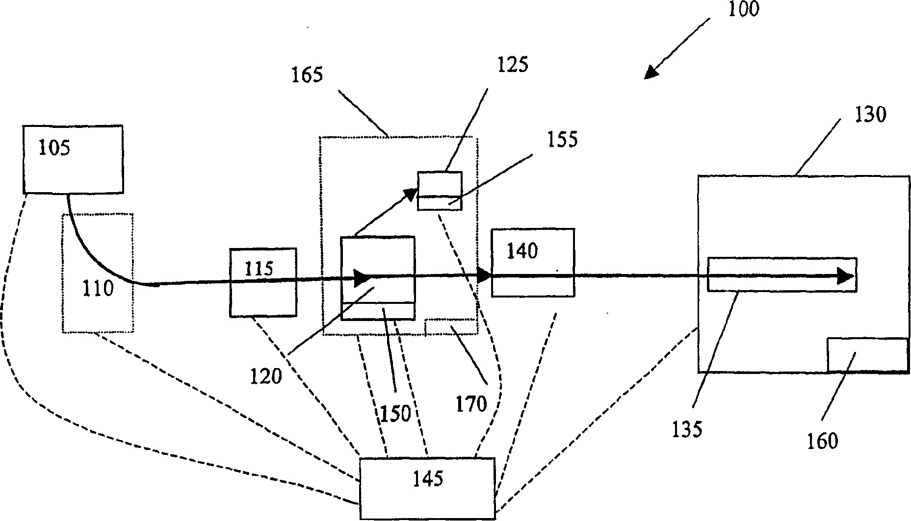
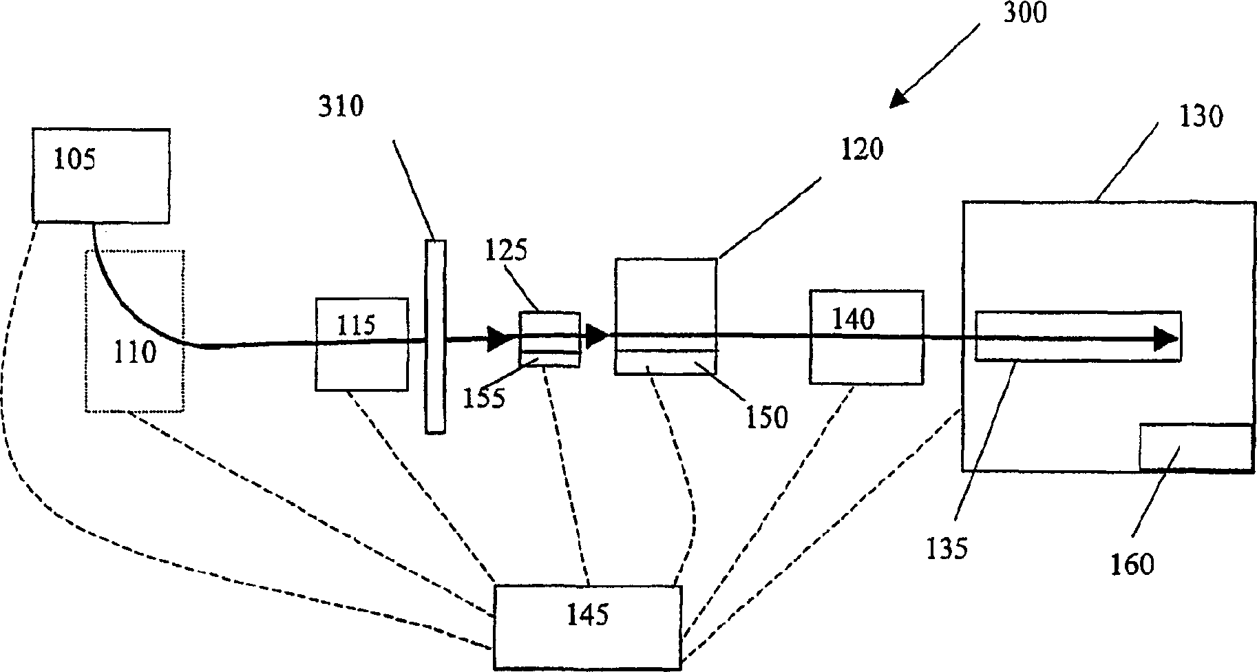
[0048] like figure 1 As shown, an apparatus / system 100 that can be used to control the number of ions in a mass analyzer 130 in accordance with one aspect of the present invention includes an ion source 115 in communication with an ion collector 120 (with associated ion collector electronics 150), A detector 125 (with associated detector electronics 155 ) and a mass analyzer 130 . Some or all of the components of system 100 are coupled to a system control unit, such as a suitably programmed digital computer 145, which receives and processes data from the various components and can be configured to analyze the received data.

[0049] Ion source 115 can be any conventional ion source, such as an ion spray or electrospray ion source, and generates ions from material received from, for example, autosampler 105 and liquid chromatograph 110 . Ions generated by ion source 115 proceed (directly or indirectly) to ion collector 120 . The ion collector 120 functions to accumulate ions ...


PUM


Abstract

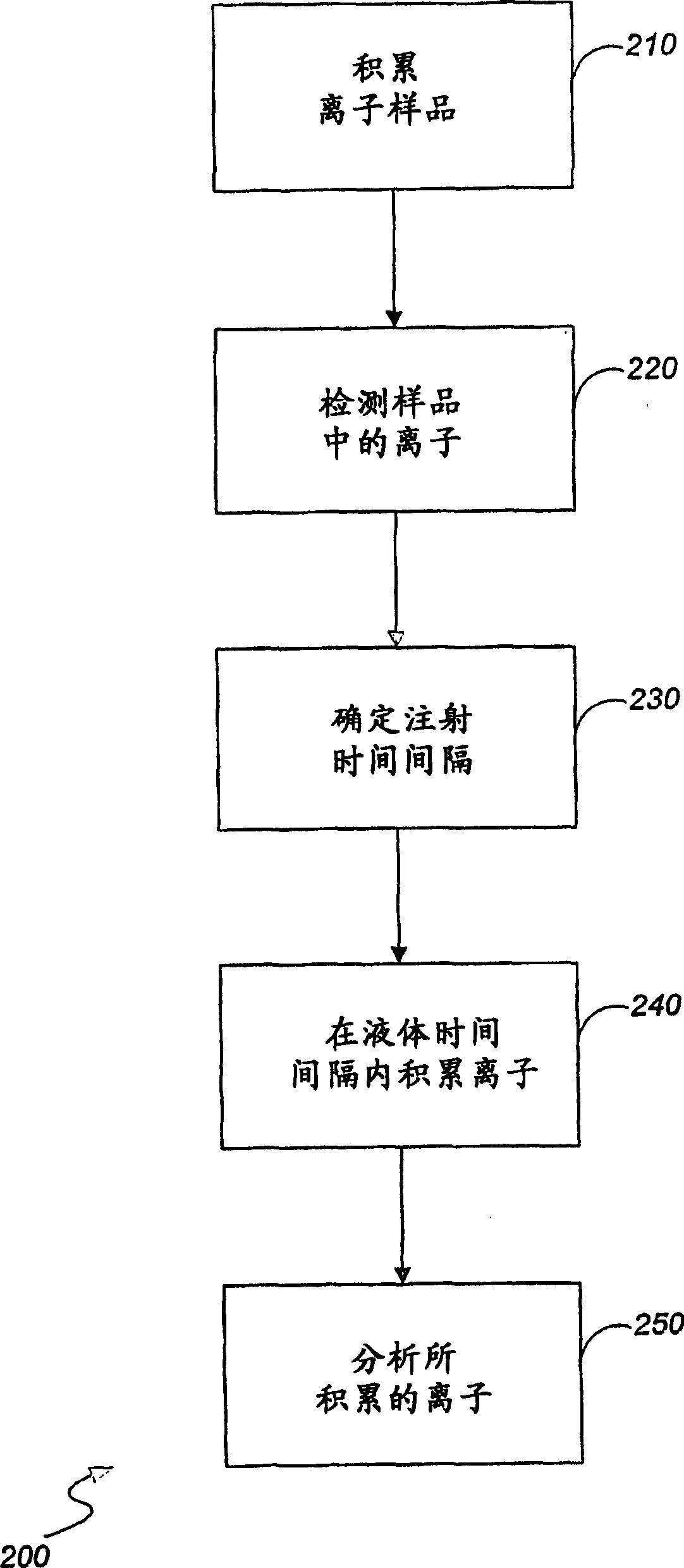
Methods and apparatus for controlling the number of ions to be analyzed in a mass analyzer are disclosed. Ions are accumulated over an injection time interval determined as a function of ion accumulation rate and a predetermined desired number of ions. Accumulation velocity represents the flow rate of ions from the ion source into the ion collector. Ions from the accumulated ions are introduced into a mass analyzer for analysis.

Description

[0001] Related patent application reference [0002] This application claims the benefit of U.S. Provisional Patent Application No. 60 / 442,368 and U.S. Provisional Patent Application No. 60 / 476,473, filed January 24, 2003, and June 5, 2003, respectively, the contents of which are incorporated herein as refer to. technical field [0003] The present invention relates to controlling the number of ions in a mass analyzer. Background technique [0004] Ion storage mass analyzers, such as RF quadrupole ion traps, ICR (ion cyclotron resonance), orbit trap (orbitrap) and FTICR (Fourier transform ion cyclotron resonance) mass analyzers, function by converting the generated The ions are transferred to a storage / trap chamber on the mass analyzer where they are analyzed. The main factor limiting the mass resolution, mass accuracy, and repeatability of such devices is space charge, which can change the storage, trapping conditions, or mass analyzer capabilities of the ICR or ion trap ...

Claims


Application Information

Patent Timeline
Patent Type & Authority Applications(China)
IPC IPC(8): H01J49/04H01J49/00H01J49/10H01J49/16H01J49/34H01J49/40H01J49/42
CPCH01J49/4265
Inventor 史蒂文·霍宁罗伯特·马力克约翰·E·赛卡安德烈亚斯·维奥斯
Owner THERMO FINNIGAN
Why Eureka
Eureka Blog
Learn More