
A preparation system and method of high-pressure mixed gas

A mixed gas and high-pressure mixing technology, applied in mixers, chemical instruments and methods, gas and gas/steam mixing, etc., can solve problems such as inability to obtain experimental data, small sample content, low gas density, etc., to ensure purity, The effect of preventing waste and improving the safety factor of high voltage

Active Publication Date: 2022-03-08
HEFEI INSTITUTES OF PHYSICAL SCIENCE - CHINESE ACAD OF SCI
View PDF10 Cites 0 Cited by
  • Summary
  • Abstract
  • Description
  • Claims
  • Application Information

AI Technical Summary

Problems solved by technology

[0003] Under normal pressure or low pressure, due to the low density of the gas, the volume will shrink severely when it reaches high pressure, and the sample content is small, and effective experimental data cannot be obtained, which cannot meet the needs

Method used


Image

  • A preparation system and method of high-pressure mixed gas
  • A preparation system and method of high-pressure mixed gas
  • A preparation system and method of high-pressure mixed gas

Examples


Embodiment 1

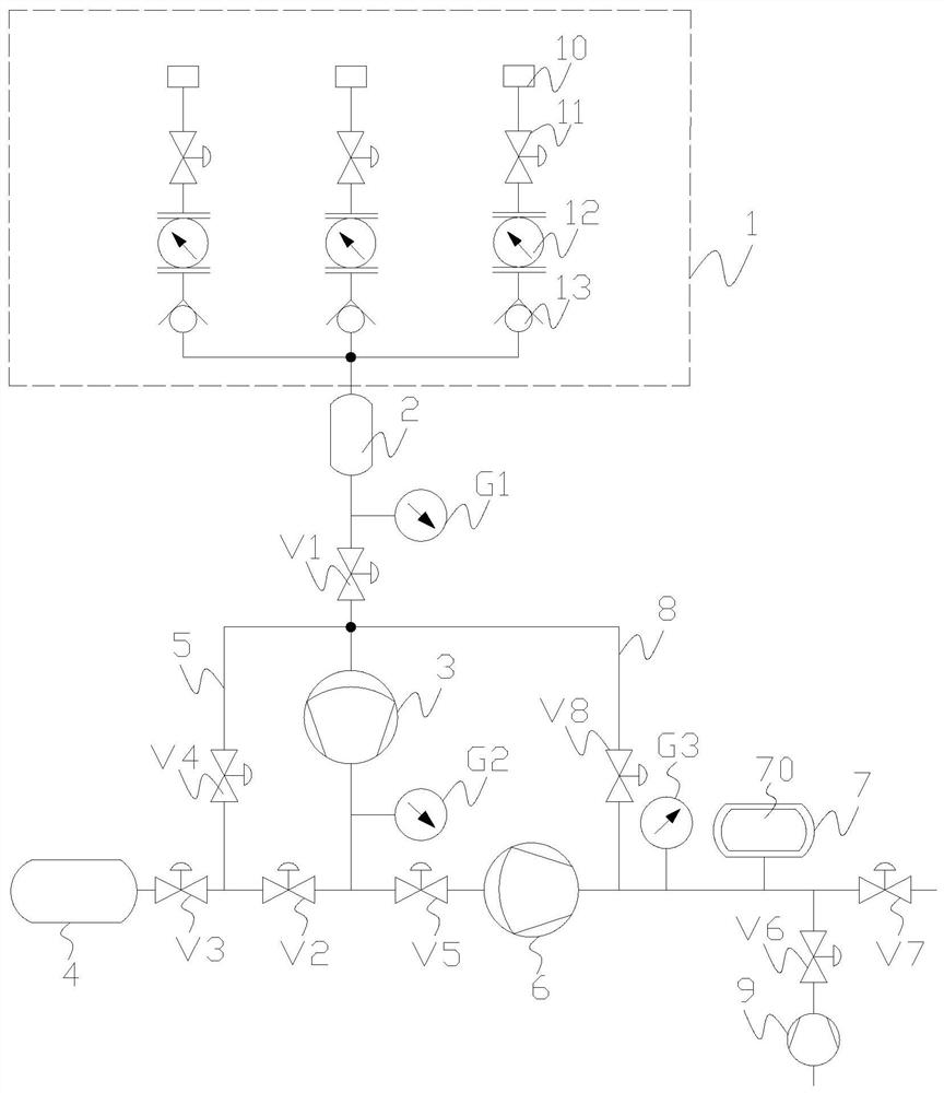
[0049] A high-pressure mixed gas preparation system, such as Figure 1a As shown, the preparation system includes a gas source control part 1, a buffer tank 2, a first supercharger 3, a mixed gas container 4, a second supercharger 6, and a sampling chamber 7. The gas source control part 1 is used to provide the preparation and mixing Various gases required for gas. The quality of the mixed gas stored in the sampling chamber 7 is less than that of the mixed gas container 4, that is, the capacity for storing the high-pressure mixed gas inside the sampling chamber 7 is smaller than the capacity for storing the high-pressure mixed gas inside the mixed gas container 4.

[0050] The air source control unit 1 includes multiple air source branches. In this embodiment, there are three types of air source branches, and each air source branch includes an air source 10, an air source valve 11, and a flow meter connected in sequence. 12. The one-way valve 13 is connected with the air inlet...

Embodiment 2

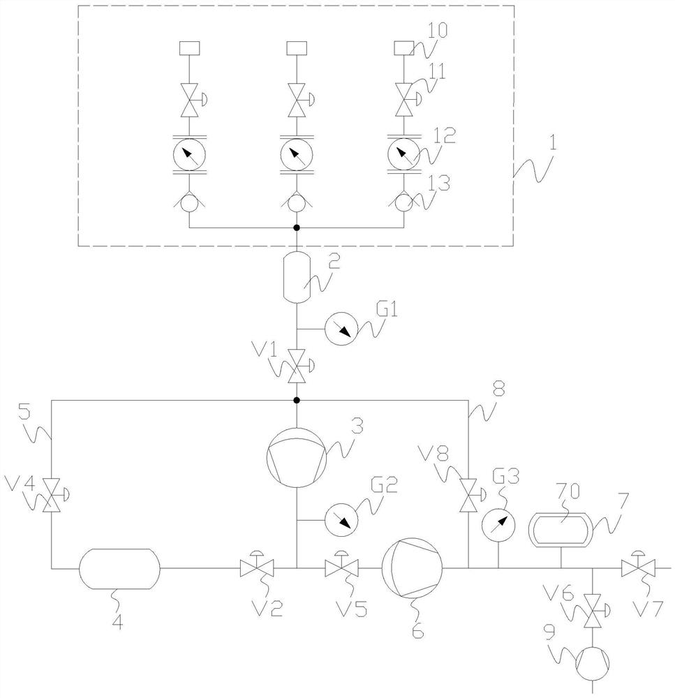
[0059] On the basis of Example 1, such as figure 2 As shown, in the present embodiment, each air source branch includes an air source 10 and an air source valve 11 connected in sequence. It communicates with the air inlet of buffer tank 2. The rest is the same as in Example 1. When preparing the mixed gas, open the gas source valve 11 of one of the gas source branches separately, and when the gas flow reaches the set value, close the gas source valve 11 of the gas source branch. Open the gas source valves 11 of other gas source branches in turn.

Embodiment 3

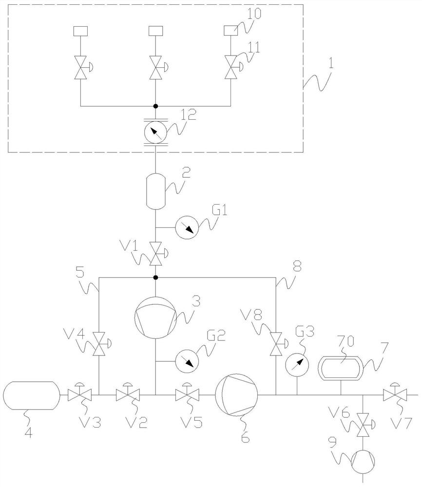
[0061] On the basis of embodiment 1, 2, as image 3 As shown, the number of mixed gas containers 4 is three groups, and the gas inlet and outlet of each mixed gas container 4 is provided with a corresponding third valve V3. When a mixed gas needs to be configured, the corresponding third valve V3 is opened. After sampling, the remaining gas is recycled to the mixed gas container 4 .


PUM


Abstract

The invention relates to the field of preparing high-pressure gas, in particular to a preparation system and a use method of high-pressure mixed gas. The preparation system includes a gas source control part, a first booster, a mixed gas container, a second booster, and a sampling chamber, and the gas source control part is used to provide various gases required for preparing the mixed gas. The gas outlet of the gas source control part communicates with the inlet of the first supercharger, the gas outlet of the first supercharger communicates with the mixed gas container, and the first supercharger and the mixed gas container cooperate with each other to control the gas source. The gas discharged by the control part is pressurized in the first stage. A gas delivery pipeline is communicated between the mixed gas container and the air inlet of the first supercharger, and the gas outlet of the first supercharger is also communicated with the air inlet of the second supercharger, and the gas outlet of the second supercharger Connected with the sampling chamber, the first supercharger, the second supercharger and the sampling chamber cooperate with each other, and are used for two-stage pressurization of the gas discharged from the mixed gas container.

Description

technical field [0001] The invention relates to the field of preparing high-pressure gas, in particular to a preparation system and a use method of high-pressure mixed gas. Background technique [0002] In the field of high-pressure science, gas is a very important research object. By changing its parameters such as temperature, pressure, and magnetic field, new physics and chemistry that do not exist under ordinary conditions can be induced, which is an important way to explore new materials. At the same time, the gas is also an excellent pressure transmission medium in a high-pressure environment, which can transmit the pressure to the solid sample more uniformly, forming an approximate hydrostatic pressure condition. [0003] Under normal pressure or low pressure, due to the low density of the gas, the volume will shrink severely when it reaches high pressure, and the sample content is small, and effective experimental data cannot be obtained, which cannot meet the needs....

Claims


Application Information

Patent Timeline
Patent Type & Authority Patents(China)
IPC IPC(8): B01F33/71B01F35/71B01F35/22B01F23/10B01F35/221B01F35/21
CPCB01F23/191B01F23/19B01F33/71B01F35/20B01F35/712
Inventor 蒋华超苏付海周浩曾雉
Owner HEFEI INSTITUTES OF PHYSICAL SCIENCE - CHINESE ACAD OF SCI
Learn More