


Quick Research
Generate reliable direction feasibility study reports for your R&D in just a few steps.

Technical Q&A
Discover and master advanced knowledge NOW. Basics, ideas, possibilities, all at once.

Find Solutions
As an expert in R&D theories, this can generate solutions to your technical problems instantly.

Evaluate Feasibility
Analyze your overall solution with one click, know your potential R&D risks in advance.

Monitor Landscape
Get weekly tech updates, stay abreast of the latest tech innovations and key insights.
Fluid jet device and method for controlling jet quality of fluid jet device
A technology of fluid injection and fluid control, which is applied to the device, printing, coating and other directions of coating liquid on the surface, which can solve the problem of insufficient data and so on
- Summary
- Abstract
- Description
- Claims
- Application Information
AI Technical Summary
Problems solved by technology
Method used
Image

Examples
no. 1 example
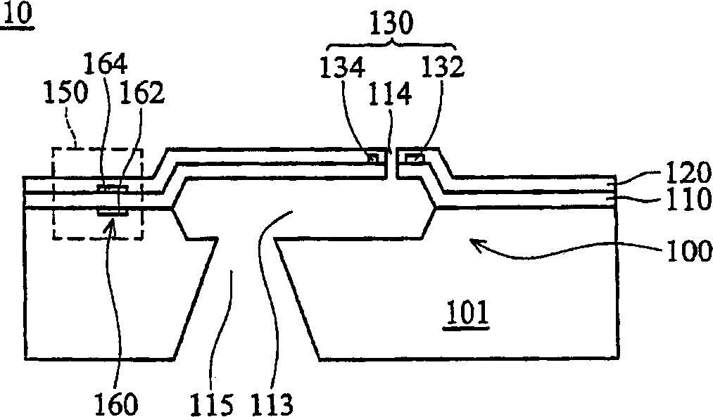
[0058] During the manufacturing process of the fluid ejection device 10A, acid (HF-49%) and alkali (KOH-30%) etchant are used to etch the substrate 100 or the sacrificial layer (not shown) of the wafer, and the structural layer 110 provides protection The role of etching solution.
[0059] To achieve the above purpose, the structure layer 110 is preferably made of low-stress (~100 MPa and tensile stress) silicon nitride deposited by LPCVD process. However, in actual fabrication, it is found that during the etching process, defects such as cracks will occur if the structure layer 110 is too thin (<0.4 um), and the surface circuits will be damaged. As for the completed device, it was also found during testing that the structural layer 110 with different thicknesses (0.6-1.2 um) has a great impact on the driving conditions of fluid ejection (including heating time or driving voltage).
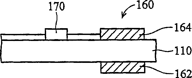
[0060] Figure 2B is a partially enlarged schematic diagram showing a sensor 150 according t...
no. 2 example
[0072] According to the object of the present invention, the present invention further provides a method for controlling the spraying quality of a fluid spraying device. As in the aforementioned microfluid ejection device, the heater is carried on the structural layer, and the heat generated by the heater is transferred to the fluid in the fluid cavity through the structural layer. According to the principle of heat transfer, the same material has the same heat transfer number k, and under the same temperature difference ΔT, the heat flux J is inversely proportional to the transfer distance L, (ie J=-k / L). Therefore, under the same driving conditions of the above-mentioned fluid ejection device, the ejection effect of the fluid ejection device will vary with the thickness of the structural layer, resulting in unstable ejection quality.
[0073] According to known techniques, the turn-on energy required for droplet firing to achieve the same jetting effect, the structural layer...
PUM
| Property | Measurement | Unit |
|---|---|---|
| Dielectric constant | aaaaa | aaaaa |
| Dielectric constant | aaaaa | aaaaa |
Abstract
Description
Claims
Application Information
 - R&D Engineer
- R&D Manager
- IP Professional
- Industry Leading Data Capabilities
- Powerful AI technology
- Patent DNA Extraction
Browse by: Latest US Patents, China's latest patents, Technical Efficacy Thesaurus, Application Domain, Technology Topic, Popular Technical Reports.
© 2024 PatSnap. All rights reserved.Legal|Privacy policy|Modern Slavery Act Transparency Statement|Sitemap|About US| Contact US: help@patsnap.com